PTFM04BH471Q2N34B0 Murata, PTFM04BH471Q2N34B0 Datasheet - Page 22
PTFM04BH471Q2N34B0
Manufacturer Part Number
PTFM04BH471Q2N34B0
Description
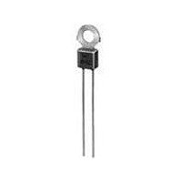
PTC THERMISTOR
Manufacturer
Murata
Series
PTFMr
Type
PTCr
Datasheet
1.PRF21BA471QB1RA.pdf
(100 pages)
Specifications of PTFM04BH471Q2N34B0
Thermistor Type
PTC
Resistance
100ohm
Operating Temperature Range
-10°C To +70°C
Operating Voltage Range
16V
Thermistor Case Style
Radial Lead
No. Of Pins
2
Length/height, External
13.2mm
External Width
7.5mm
Tolerance
20 %
Termination Style
Radial
Current Rating
0.1 Amp
Dimensions
4 mm Dia.
Voltage
16 V
Rohs Compliant
Yes
Lead Free Status / RoHS Status
Lead free / RoHS Compliant
Lead Free Status / RoHS Status
Lead free / RoHS Compliant
Available stocks
Company
Part Number
Manufacturer
Quantity
Price
Company:

Part Number:
PTFM04BH471Q2N34B0
Manufacturer:
MURATA
Quantity:
1 140


1
!Note
20
No.
10
(*) Measure resistance after the test by applying voltage of less than 1.5Vdc by a direct current of less than 10mA after product is left at 25±2°C for 2 hours.
Above mentioned soldering in "4. Adhesive Strength" and "5. Vibration" is done under the following conditions at our site.
Chip Type Specifications and Test Methods
1
2
3
4
5
6
7
8
9
Specifications and Test Methods
PRG18/21BB Series
#Glass-Epoxy PC board
#Standard land dimension
#Standard solder paste
#Standard solder profile
Above conditions are mentioned in Notice.
Operating Temp.
Resistance Value (at 25°C)
Withstanding Voltage
Adhesive Strength
Vibration
Solderability
Solder-heatability
Temperature Cycling
Humidity Test
High Temperature
Load Test
• Please read rating and !CAUTION (for storage, operating, rating, soldering, mounting and handling) in this catalog to prevent smoking and/or burning, etc.
• This catalog has only typical specifications because there is no space for detailed specifications. Therefore, please review our product specifications or consult the approval sheet for product specifications before ordering.
Item
-10 to 60°C
The resistance value should be within the specified
tolerance.
Without damage
There is no sign of exfoliation on electrode.
Normal appearance
Resistance change: not to exceed ±20% (*)
Min. 75% electrode is covered with new solder.
Resistance change: not to exceed ±20% (*)
Normal appearance
Resistance change: not to exceed ±20% (*)
Normal appearance
Resistance change: not to exceed ±20% (*)
Normal appearance
Resistance change: not to exceed ±20% (*)
Normal appearance
Resistance change: not to exceed ±20% (*)
Rating Value
Temperature range with maximum voltage applied to PTC.
After applying maximum operating voltage for 3 mins. and
leaving for 2 hrs. in 25°C, measured by applying voltage of less
than 1.5Vdc (by a direct current of less than 10mA).
We apply 120% of the maximum operating voltage to PTC by
raising gradually for 180±5 secs. at 25°C. (A protective resistor
is to be connected in series, and the inrush current through
PTC must be limited below maximum rated value.)
EIAJ ET-7403 term 9
Soldered PTC to PCB and add a force of 5.0N in the direction
as shown below.
JIS C 5102 term 8.2
JIS C 5102 term 8.4
JIS C 5102 term 9.3
Times: 5 cycles
JIS C 5102 term 9.5
40±2°C, 90-95%RH leave for 500±4 hrs.
JIS C 5102 term 9.10
60±3°C (in air), PTC is applied maximum operating voltage for 1.5
hrs. on and 0.5 hrs. off. This cycle is repeated for 1000±10 hrs.
Soldered PTC to PCB
Vibration: A 10-55-10Hz (1 min.)
Width: 1.5mm
Vibrate for 2 hrs. in each of 3 mutually perpendicular planes
for a total of 6 hrs.
Solder: Sn 63%/Pb 37% (or 60/40%)
Solder temp: 230±5°C
Soaking time: 3±0.5 secs.
Soaking position: Until a whole electrode is soaked
Solder: Sn 63%/Pb 37% (or 60/40%)
Flux: Solder paste containing less than 0.2wt% of chlorine.
Preheating: 150±5°C 3 mins.
Peak temp.: 260±5°C 10±5 secs. (reflow)
PCB: Glass Epoxy PCB (JIS C 6484)
Step
1
2
3
4
Room temp.
Room temp.
Temp. (°C)
+85 +3, -0
-20 +0, -3
Method of Examination
PTC
F
Time (min.)
10-15
10-15
30
30
Glass Epoxy PCB
F=5.0N
F
Apr.25,2011
R90E.pdf
Related parts for PTFM04BH471Q2N34B0
Image
Part Number
Description
Manufacturer
Datasheet
Request
R

Part Number:
Description:
Murata Microblower 20x20 DCDC Driver Board - Samples Only
Manufacturer:
Murata
Part Number:
Description:
357-036-542-201 CARDEDGE 36POS DL .156 BLK LOPRO
Manufacturer:
Murata
Datasheet:
Part Number:
Description:
Manufacturer:
Murata
Datasheet:
Part Number:
Description:
Manufacturer:
Murata
Datasheet:
Part Number:
Description:
Manufacturer:
Murata
Datasheet:
Part Number:
Description:
Manufacturer:
Murata
Datasheet:
Part Number:
Description:
Manufacturer:
Murata
Datasheet:
Part Number:
Description:
Manufacturer:
Murata
Datasheet:
Part Number:
Description:
Manufacturer:
Murata
Datasheet:
Part Number:
Description:
BLM21BD751SN1On-Board Type (DC) EMI Suppression Filters
Manufacturer:
Murata
Datasheet:
Part Number:
Description:
BLM15AG100SN1On-Board Type (DC) EMI Suppression Filters
Manufacturer:
Murata
Datasheet:
Part Number:
Description:
NFE31PT222Z1E9On-Board Type (DC) EMI Suppression Filters
Manufacturer:
Murata
Datasheet:
Part Number:
Description:
Chip Coil
Manufacturer:
Murata
Datasheet:
Part Number:
Description:
Chip Coil
Manufacturer:
Murata
Datasheet: