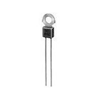
PTFM04BH471Q2N34B0 Murata, PTFM04BH471Q2N34B0 Datasheet - Page 77

PTFM04BH471Q2N34B0
Manufacturer Part Number
PTFM04BH471Q2N34B0
Description
PTC THERMISTOR
Manufacturer
Murata
Series
PTFMr
Type
PTCr
Datasheet
1.PRF21BA471QB1RA.pdf
(100 pages)
Specifications of PTFM04BH471Q2N34B0
Thermistor Type
PTC
Resistance
100ohm
Operating Temperature Range
-10°C To +70°C
Operating Voltage Range
16V
Thermistor Case Style
Radial Lead
No. Of Pins
2
Length/height, External
13.2mm
External Width
7.5mm
Tolerance
20 %
Termination Style
Radial
Current Rating
0.1 Amp
Dimensions
4 mm Dia.
Voltage
16 V
Rohs Compliant
Yes
Lead Free Status / RoHS Status
Lead free / RoHS Compliant
Lead Free Status / RoHS Status
Lead free / RoHS Compliant
Available stocks
Company
Part Number
Manufacturer
Quantity
Price
Company:
Part Number:
PTFM04BH471Q2N34B0
Manufacturer:
MURATA
Quantity:
1 140
!Note
No.
*: The resistance value after the test. It is measured by applying voltage less than DC1.0V after left at 25 2 C for 2hrs.
**: Above mentioned soldering is done under the following conditions at our side.
1
2
3
4
5
6
7
8
9
PRF15_102R Series
· Glass-Epoxy PC board
· Standard land dimension
· Standard solder paste
· Standard solder profile
Above conditions are mentioned in Notice.
Resistance Value at 25 C
Vibration
Solderability
Resistance to Soldering Heat
High Temperature Storage
Low Temperature Storage
Damp Heat, Steady State
Thermal Shock
High Temperature Load
• Please read rating and !CAUTION (for storage, operating, rating, soldering, mounting and handling) in this catalog to prevent smoking and/or burning, etc.
• This catalog has only typical specifications because there is no space for detailed specifications. Therefore, please review our product specifications or consult the approval sheet for product specifications before ordering.
Overheat Sensing Chip Tight Tolerance Type Specifications and Test Methods
Item
Within the specified range
• Resistance (R25) change: Less than 20% (*)
• Appearance: No defects or abnormalities
Wetting of soldering area: U95%
· Appearance: No defects or abnormalities
· Resistance (R25) change: Less than 20% (*)
· Appearance: No defects or abnormalities
· Resistance (R25) change: Less than 20% (*)
Creteria
After applying maximum operating voltage for 3 mins. and
leaving for 2 hours in 25 C, measured by applying voltage less
than DC1.0V.
Reference standard: IEC 60068-2-6 (1995)
· Soldered PTC to PCB (**)
· Frequency range: 10 to 55Hz
· Amplitude: 1.5mm
· Sweep rate: 1octave/min.
· Direction: X-Y-Z (3 direction)
· 24 cycles in each axis
Reference standard: IEC 60068-2-58 (2004)
· Solder: Sn-3.0Ag-0.5Cu
· Solder temp.: 245 5 C
· Immersion time: 3 0.3s
Reference standard: IEC 60068-2-58 (2004)
[ Solder bath method ]
· Solder: Sn-3.0Ag-0.5Cu
· Preheat: 150 5 C, 90 to 120s
· Solder temp.: 260 5 C
· Immersion time: 10 1s
Reference standard: IEC 60068-2-2 (2007)
· Soldered PTC to PCB (**)
· (Max. operating temp.) 2 C
· 1000+48/-0 hrs.
Reference standard: IEC 60068-2-1 (2007)
· Soldered PTC to PCB (**)
· (Min. operating temp.) 3 C
· 1000+48/-0 hrs
Reference standard: IEC 60068-2-67 (1995)
· Soldered PTC to PCB (**)
· +85 2 C, 85 5%RH
· 1000+48/-0 hrs
Reference standard: IEC 60068-2-14 (2009)
[ Test Na ]
· Soldered PTC to PCB (**)
· Transport time: <10 sec.
· Test condition: See below table
· Test cycle: 5 cycles
Reference standard: IEC 60068-2-2 (2007)
· Soldered PTC to PCB (**)
· (Max. operating temp.) 2 C
· Applied max. voltage
· 1000+48/-0 hrs.
Step
1
2
(Max. Operating temp.) 2 C
(Min. Operating temp.) 3 C
Test Conditions
Condition
30min.
30min.
Time
75
Apr.25,2011
R90E.pdf
11


