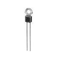
PTFM04BH471Q2N34B0 Murata, PTFM04BH471Q2N34B0 Datasheet - Page 94

PTFM04BH471Q2N34B0
Manufacturer Part Number
PTFM04BH471Q2N34B0
Description
PTC THERMISTOR
Manufacturer
Murata
Series
PTFMr
Type
PTCr
Datasheet
1.PRF21BA471QB1RA.pdf
(100 pages)
Specifications of PTFM04BH471Q2N34B0
Thermistor Type
PTC
Resistance
100ohm
Operating Temperature Range
-10°C To +70°C
Operating Voltage Range
16V
Thermistor Case Style
Radial Lead
No. Of Pins
2
Length/height, External
13.2mm
External Width
7.5mm
Tolerance
20 %
Termination Style
Radial
Current Rating
0.1 Amp
Dimensions
4 mm Dia.
Voltage
16 V
Rohs Compliant
Yes
Lead Free Status / RoHS Status
Lead free / RoHS Compliant
Lead Free Status / RoHS Status
Lead free / RoHS Compliant
Available stocks
Company
Part Number
Manufacturer
Quantity
Price
Company:
Part Number:
PTFM04BH471Q2N34B0
Manufacturer:
MURATA
Quantity:
1 140
12
!Note
92
!Caution/Notice
Allowable Flow Soldering Temp. and Time
Flow Soldering Conditions
(2) Adhesive Application and Curing
(4) Recommendable Temperature Profile for Soldering
(5) There may be a risk of unexpected failures
Continued from the preceding page.
(a) If insufficient adhesive is applied, or if the adhesive
(b) Too low viscosity of adhesive causes this product to
(a) Insufficient preheating may cause a crack on the
(b) Rapid cooling by dipping in solvent or by other
(tombstone, insufficient solder-wetting, etc.) in the
mounting process caused by the mounting conditions.
Please make sure that this product is correctly mounted
under the specified mounting conditions.
• Please read rating and !CAUTION (for storage, operating, rating, soldering, mounting and handling) in this catalog to prevent smoking and/or burning, etc.
• This catalog has only typical specifications because there is no space for detailed specifications. Therefore, please review our product specifications or consult the approval sheet for product specifications before ordering.
200
100
is not sufficiently hardened, this product may have a
loose contact with the land, during flow soldering.
slip on the board, after mounting.
ceramic body. Difference between preheating
temperature and maximum temperature in the profile
should be 100 C.
means is not recommended.
0
* In case of repeated soldering, the accumulated soldering
time should be within the range shown above figure (3).
Preheating: 150 10 C, 1-2 minutes.
Soldering: 250 C, 3 sec.
270
260
250
240
230
220
210
200
Preheating (in air)
0
1 to 2 min.
10
Time (sec.)
Soldering
20
*3 sec.
250 C
Gradual cooling
30
(in air)
Allowable Reflow Soldering Temp. and Time
Reflow Soldering Conditions
(3) Allowable Soldering Temperature and Time
(a) Solder within the temperature and time
(b) Excessive soldering conditions may cause
(c) In case of repeated soldering, the accumulated
200
100
combinations, indicated by the slanted lines in the
following graphs.
dissolution of metallization or deterioration of solder-
wetting on the external electrode.
soldering time should be within the range shown
below figure. (For example, Reflow peak temperature:
260 C, twice – > The accumulated soldering time at
260 C is within 30sec. )
0
* In case of repeated soldering, the accumulated soldering
time should be within the range shown above figure (3).
Preheating: 150 10 C, 1-2 minutes.
Soldering: 250 C, 20 sec.
280
270
260
250
240
230
220
210
Preheating (in air)
0
10
20 30 40 50 60 70
1 to 2 min.
Time (sec.)
Soldering
*20 sec.
250 C
80
90
100
Gradual cooling
110
(in air)
Apr.25,2011
R90E.pdf


