DP-101-E-P SUNX, DP-101-E-P Datasheet - Page 12
DP-101-E-P
Manufacturer Part Number
DP-101-E-P
Description
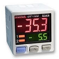
PRESSURE SENSOR, -1TO1BAR, PNP, 2M
Manufacturer
SUNX
Datasheet
1.DP-101A-E-P.pdf
(16 pages)
Specifications of DP-101-E-P
Svhc
No SVHC (18-Jun-2010)
Response Time
2.5ms
Contact Configuration
Connecting Cable, 2m
External Depth
42.5mm
External Length / Height
30mm
External Width
30mm
Ip/nema Rating
IP40
Lead
RoHS Compliant


11
I/O CIRCUIT AND WIRING DIAGRAMS
I/O circuit diagram
I/O circuit diagram
Multi-function type
Multi-function type
Standard type
Standard type
Symbols
Symbols
Symbols
Symbols
NPN output type
PNP output type
5 V
T
T
T
T
T
T
r
r
r
r
r
2
r
2
1
1
2
-
1
T
T
r
r
1
2
Internal circuit
Internal circuit
Internal circuit
Internal circuit
1 kΩ
1 kΩ
D : Reverse supply polarity protection diode
Z
T
D
Z
T
T
D : Reverse supply polarity protection diode
Z
T
D
Z
T
T
D1
r1
D1
r1
r2
D1
r1
D1
r1
r2
1
1
, D
, D
, T
D
, T
D
, Z
, Z
: Surge absorption zener diode
: PNP output transistor
: NPN input transistor
: Surge absorption zener diode
: PNP input transistor
: NPN output transistor
1
D
r2
2
r2
D
2
Z
Z
Z
D2
D2
2
D2
D1
D1
2
: Reverse supply polarity protection diode
: Reverse supply polarity protection diode
: PNP output transistor
: Surge absorption zener diode
: NPN output transistor
: Surge absorption zener diode
Z
Z
Z
D
D
D2
D1
D1
1
1
2
3
4
1
2
3
4
1
3
2
4
1
2
3
4
(Black) Comparative output 1
(White) Analog voltage output
(Brown)
(Black)
Comparative output 1
(White) Comparative output 2
(Blue) 0 V
(Brown)
(White) Analog voltage output
(Black) Comparative output 1
(Blue) 0 V
(Brown)
(Black) Comparative output 1
(White) Comparative output 2
(Blue) 0 V
(Brown)
(Blue) 0 V
Terminal No.
Terminal No.
Terminal No.
Terminal No.
Color code of connector attached cable
Color code of connector attached cable
Color code of connector attached cable
Color code of connector attached cable
Users’ circuit
Users’ circuit
Users’ circuit
Users’ circuit
100 mA max.
100 mA max.
or External input
or External input
100 mA max.
V
V
V
V
100 mA max.
Load
100 mA max.
100 mA max.
Load
Load
Load
Load
Load
12 to 24 V DC
12 to 24 V DC
12 to 24 V DC
12 to 24 V DC
10 %
10 %
10 %
10 %
Terminal arrangement diagram
Terminal arrangement diagram
Terminal
Terminal
1
2
3
4
1
2
3
4
1
1
Standard type:
Multi-function type: Analog voltage output or External input
Standard type:
Multi-function type: Analog voltage output or External input
2
2
3
3
Comparative output 2
Comparative output 2
4
4
Comparative output 1
Comparative output 1
Designation
Designation
0 V
0 V
V
V
Related parts for DP-101-E-P
Image
Part Number
Description
Manufacturer
Datasheet
Request
R


Part Number:
Description:
DP-Power Controller, 6A N-Channel MOSFET Driver
Manufacturer:
Linear Technology
Datasheet:

Part Number:
Description:
ANTENNA PREC DIPOLE 880-925MHZ
Manufacturer:
TDK Corporation
Datasheet:
Part Number:
Description:
ANTENNA PREC DIPOLE 1710-1785MHZ
Manufacturer:
TDK Corporation
Datasheet:
Part Number:
Description:
ANTENNA PREC DIPOLE 1850-1910MHZ
Manufacturer:
TDK Corporation
Datasheet:
Part Number:
Description:
ANTENNA PREC DIPOLE 1920-1980MHZ
Manufacturer:
TDK Corporation
Datasheet:
Part Number:
Description:
ANTEN PREC DIPOLE 2400-2483.5MHZ
Manufacturer:
TDK Corporation
Datasheet:

Part Number:
Description:
DP-MINIATURE BREAKER 1P 1A C CURVE SCREW TERMINAL
Manufacturer:
MOELLER
Part Number:
Description:
DP-SWREG/Controller, Hi Eff Syn Stepdn Sw Reg
Manufacturer:
Linear Technology
Part Number:
Description:
DP-LINREG, 500mA VLDO In 2x2 DFN
Manufacturer:
Linear Technology
Part Number:
Description:
DP-Charge Pump/LED Driver, Main/Cam LED Controller In QFN
Manufacturer:
Linear Technology
Part Number:
Description:
DP-Charge Pump/LED Driver, Main/Cam LED Controller In QFN
Manufacturer:
Linear Technology
Part Number:
Description:
DP-SWREG/Monolithic, Dual 1.5A & 1A, 4MHz Synchronous Step-Down DC/DC Converter
Manufacturer:
Linear Technology