DP-101-E-P SUNX, DP-101-E-P Datasheet - Page 13
DP-101-E-P
Manufacturer Part Number
DP-101-E-P
Description
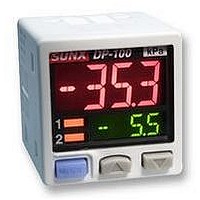
PRESSURE SENSOR, -1TO1BAR, PNP, 2M
Manufacturer
SUNX
Datasheet
1.DP-101A-E-P.pdf
(16 pages)
Specifications of DP-101-E-P
Svhc
No SVHC (18-Jun-2010)
Response Time
2.5ms
Contact Configuration
Connecting Cable, 2m
External Depth
42.5mm
External Length / Height
30mm
External Width
30mm
Ip/nema Rating
IP40
Lead
RoHS Compliant


PRECAUTIONS FOR PROPER USE
Wiring
•
•
•
•
•
•
Connection
•
Conditions in use for CE conformity
•
•
Mounting
•
•
Front protection cover
MS-DP1-3 (Optional)
Condition
Make sure that the power supply is off while wiring.
Verify that the supply voltage variation is within the rating.
If power is supplied from a commercial switching regulator, ensure
that the frame ground (F.G.) terminal of the power supply is
connected to an actual ground.
In case noise generating equipment (switching regulator, inverter
motor, etc.) is used in the vicinity of this sensor, connect the frame
ground (F.G.) terminal of the equipment to an actual ground.
Do not run the wires together with high-voltage lines or power lines
or put them in the same raceway. This can cause malfunction due
to induction.
Incorrect wiring will cause problems with operation.
Do not apply stress directly to the
connection cable leader or to the
connector.
The DP-100 series is a CE conformity product complying with
EMC Directive. The harmonized standard with regard to immunity
that applies to this product is EN 61000-6-2 and the following
condition must be met to conform to that standard.
The sensor should be connected less than 10 m
power supply.
The MS-DP1-1 sensor mounting bracket is available separately,
and it should be used for mounting. When tightening the sensor to
the sensor mounting bracket, use a tightening torque of 0.5 N m or
less.
The MS-DP1-2 panel mounting bracket (optional) and the
MS-DP1-3 front protection cover (optional) are also available.
Sensor mounting bracket
MS-DP1-1 (Optional)
•
•
•
Never use this product as a sensing device for
personnel protection.
In case of using sensing devices for personnel
protection, use products which meet regulations and
standards, such as OSHA, ANSI or IEC etc., for
personnel protection applicable in each region or
country.
The DP-100 series is designed for use with non-
corrosive gas. It cannot be used with liquid or
corrosive gas.
M3 (length 6 mm
screws with washers
(Accessory for MS-DP1-1)
Panel mounting bracket
MS-DP1-2 (Optional)
0.236
in)
M3 (length 12 mm
tapping screw
(Accessory for MS-DP1-2)
32.808 ft
Connector
attached cable
(CN-14A-C )
from the
0.472
in)
Piping
•
Others
•
•
•
•
•
•
•
RUN mode
• This is the normal operating mode.
MENU SETTING mode
•
•
Comparative output 1
output mode setting
Comparative output 2 output mode
setting (standard type only)
Analog voltage output /
external input switching
(multi-function type only)
NO / NC switching
Response time setting
Display color switching
for main display
Unit switching
If connecting a commercially-available
coupling to the pressure port, attach a
12 mm
spanner for DP-100-E type) to the hexagonal
section of the pressure port to secure it, and
tighten at a torque of 9.8 N m or less. If it is
tightened using excessive torque, it may
damage the coupling or the pressure port.
In addition, wrap sealing tape around the
coupling when connecting it to prevent leaks.
Use within the rated pressure range.
Do not apply pressure exceeding the pressure withstandability
value. The diaphragm will get damaged and correct operation shall
not be maintained.
Do not use during the initial transient time (0.5 sec. approx.) after
the power supply is switched on.
Avoid dust, dirt, and steam.
Take care that the sensor does not come in direct contact with
water, oil, grease, or organic solvents, such as, thinner, etc.
Do not insert wires, etc., into the pressure port. The diaphragm will
get damaged and correct operation shall not be maintained.
Do not operate the keys with pointed or sharp objects.
If the mode selection key is pressed and held for 2 seconds in
RUN mode, the mode will switch to MENU SETTING mode.
If the mode selection key is pressed while a setting is being made,
the mode will switch to RUN mode. In this case, the settings that
have been changed will be entered.
Threshold value
setting
Zero-adjustment
function
Key lock function
Peak hold /
bottom hold function
Setting item
Setting item
0.472 in
spanner (14 mm
The threshold values for ON / OFF operation can be changed directly
by pressing the increment key (UP) and the decrement key (DOWN).
This forces the pressure value display to be reset to zero when
the pressure port is open on the atmospheric pressure side.
Stops key operations from being accepted.
Displays the peak value and bottom value for fluctuating
pressure. The peak value appears in the main display,
and the bottom value appears in the sub display.
Sets the output mode for comparative output 1.
Sets the output mode for comparative output 2.
Allows switching between analog voltage output
and auto-reference input / remote zero-adjust-
ment input.
Sets normally open (NO) or normally closed (NC).
Sets the response time.
The response time can be selected from 2.5 ms,
5 ms, 10 ms, 25 ms, 50 ms, 100 ms, 250 ms,
500 ms, 1,000 ms and 5,000 ms.
Allows the color for the main display to be changed.
The colors can be set to ‘red / green’ or ‘green / red’
to correspond to ON / OFF output, or it can be fixed
at ‘red’ or ‘green’ all the time.
Pressure unit can be changed.
0.551 in
Description
Description
12 mm
spanner
-
0.472 in
12
Related parts for DP-101-E-P
Image
Part Number
Description
Manufacturer
Datasheet
Request
R


Part Number:
Description:
DP-Power Controller, 6A N-Channel MOSFET Driver
Manufacturer:
Linear Technology
Datasheet:

Part Number:
Description:
ANTENNA PREC DIPOLE 880-925MHZ
Manufacturer:
TDK Corporation
Datasheet:
Part Number:
Description:
ANTENNA PREC DIPOLE 1710-1785MHZ
Manufacturer:
TDK Corporation
Datasheet:
Part Number:
Description:
ANTENNA PREC DIPOLE 1850-1910MHZ
Manufacturer:
TDK Corporation
Datasheet:
Part Number:
Description:
ANTENNA PREC DIPOLE 1920-1980MHZ
Manufacturer:
TDK Corporation
Datasheet:
Part Number:
Description:
ANTEN PREC DIPOLE 2400-2483.5MHZ
Manufacturer:
TDK Corporation
Datasheet:

Part Number:
Description:
DP-MINIATURE BREAKER 1P 1A C CURVE SCREW TERMINAL
Manufacturer:
MOELLER
Part Number:
Description:
DP-SWREG/Controller, Hi Eff Syn Stepdn Sw Reg
Manufacturer:
Linear Technology
Part Number:
Description:
DP-LINREG, 500mA VLDO In 2x2 DFN
Manufacturer:
Linear Technology
Part Number:
Description:
DP-Charge Pump/LED Driver, Main/Cam LED Controller In QFN
Manufacturer:
Linear Technology
Part Number:
Description:
DP-Charge Pump/LED Driver, Main/Cam LED Controller In QFN
Manufacturer:
Linear Technology
Part Number:
Description:
DP-SWREG/Monolithic, Dual 1.5A & 1A, 4MHz Synchronous Step-Down DC/DC Converter
Manufacturer:
Linear Technology