PGMMOD00 Red Lion Controls, PGMMOD00 Datasheet - Page 7
PGMMOD00
Manufacturer Part Number
PGMMOD00
Description
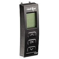
Display Programming Module
Manufacturer
Red Lion Controls
Datasheet
1.PGMMOD00.pdf
(12 pages)
Specifications of PGMMOD00
Accessory Type
Display Programming Module
Module Type
Programming/Display
For Use With
IAMS Universal Signal Conditioning Modules
Lead Free Status / RoHS Status
Lead free / RoHS Compliant


5.1 MODULE 1 - S
Select the appropriate Input Type for the application.
Note: Changing the input parameters may affect the setpoint and/or
MINIMUM RESISTANCE (
VOLTAGE RANGE (
CURRENT RANGE (
WIRE CONNECTION (
analog programming.
signal. This selection should be high enough to avoid input signal
overload but low enough for the desired input resolution.
Select the appropriate Voltage Range that corresponds to the external
Select the appropriate Current Range that corresponds to the external
signal. This selection should be high enough to avoid input signal
overload but low enough for the desired input resolution.
Select the wires the sensor or signals has to connect to the unit.
Enter the low resistance value.
INPUT TYPE (
to
parameters appear.
parameters appear.
following parameters appear.
PARAMETER MENU - VOLTAGE, CURRENT AND POTENTIOMETER
INPUT TYPE (
INPUT TYPE (
INPUT TYPE (
If input type is selected for voltage, the following
If input type is selected for current, the following
If input type is selected for linear resistance, the
)
)
)
)
PARAMETER MENU - TEMPERATURE
IGNAL
)
)
)
)
I
NPUT
7
P
resistance and potentiometer input types.
ARAMETERS
The next five parameters apply to the voltage, current, linear
Select the appropriate decimal point location.
Enter the low display value.
Enter the high display value.
MAXIMUM RESISTANCE (
Enter the high resistance value.
UNIT IDENTIFICATION (
Select one of the 69 available units as listed below.
to
to
DISPLAY HIGH (
DISPLAY LOW (
DECIMAL POINT (
to
)
)
)
)
)
Related parts for PGMMOD00
Image
Part Number
Description
Manufacturer
Datasheet
Request
R

Part Number:
Description:
Counter
Manufacturer:
Red Lion Controls
Datasheet:
Part Number:
Description:
Miniature Length Sensor
Manufacturer:
Red Lion Controls
Datasheet:
Part Number:
Description:
Model Lsc - Single Channel Output Length Sensor
Manufacturer:
Red Lion Controls
Datasheet: