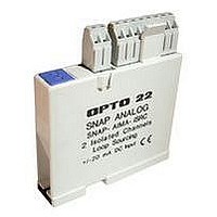
SNAP-AIPM OPTO 22, SNAP-AIPM Datasheet - Page 6

SNAP-AIPM
Manufacturer Part Number
SNAP-AIPM
Description
Power Monitoring Module
Manufacturer
OPTO 22
Type
Inputr
Specifications of SNAP-AIPM
Accessory Type
Single-phase Power Monitoring Module
Leaded Process Compatible
No
Peak Reflow Compatible (260 C)
No
Signal Input Type
85 To 250V And 0 To 10A RMS
Brand/series
SNAP Series
Connection To Host
Backplane
Current, Input
100 mA
Current, Supply
0 to 10 A
Dimensions
82.55mmL×18.29mmW×90.17mmH
Input
85 to 250/0 to 10 VAC/AAC
Input Resolution
10 mV
Input Type
Analog
Input, Range
85 to 250/0 to 10 VAC/AAC
Mounting Type
PCB
Number Of Channels
2
Number Of Inputs
2 Channels
Primary Type
Control
Resistance, Input
1 Megohms
Special Features
Transformer Isolation, Optical Isolation
Standards
UL, CSA, CE Certified
Temperature, Operating
0 to +70 °C
Voltage, Isolation
4000 V
Voltage, Supply
5 VDC
No. Of Analog Inputs
4
Resolution
10mV, 400uA
Rohs Compliant
No
For Use With
Snap I/O Modules
Lead Free Status / RoHS Status
Contains lead / RoHS non-compliant
PAGE
6
Scaling
If you are using PAC Control, when you configure the points on
SNAP power monitoring modules, you must scale them to
match the CT you use. Scaling must be accurate for the
resulting data to be accurate. The examples starting on
can help you determine the correct values for your CT and
module.
IMPORTANT: For all installations of 85 to 250 VAC, both Actual
and Scaled Volts (point 0 on all modules, plus points 4 and 8
on the SNAP-AIPM-3 and SNAP-AIPM-3V) should remain at
the default of 0–250 VAC.
However, for installations over 250 VAC (such as lighting
systems using 277 volts), you will need to scale these points.
For help, see
with PT” on page 7
PT” on page
than 250 VAC require you to use a step-down potential
transformer.
Steps for Scaling Modules in PAC Control
1.
2.
3.
Opto 22 • 43044 Business Park Drive • Temecula, CA 92590-3614 • www.opto22.com
© 2006–2011 Opto 22. All rights reserved. Dimensions and specifications are subject to change. Brand or product names used herein are trademarks or registered trademarks of their respective companies or organizations.
For the SNAP-AIPM, you see four points. For the SNAP-AIPM-3
(shown above) or the SNAP-AIPM-3V, you see 14. You must
configure each point.
In PAC Control, open your strategy. In the Strategy Tree,
right-click the I/O unit containing the power monitoring
module and choose Configure from the popup menu.
Click the I/O points button. Double-click the module’s
position number on the rack. Click Analog Input and
then choose the module’s part number from the list.
Click OK.
Click the plus sign next to the module to open its points.
8. Note that these examples of line voltage higher
“Scaling Example 2: SNAP-AIPM or SNAP-AIPM-3
or
“Scaling Example 4: SNAP-AIPM-3V with
page 7
4.
5.
6.
Double-click point 0, the voltage input, and give it a
name. If you’re not using a PT, leave the scaling as is. The
following image illustrates point 0 for Scaling Example 1
on
Click OK.
Continue to configure each point on the module,
following the calculations in the examples on the next
two pages. (For SNAP-AIPM-3V, see the examples on
page
page
8.) Here is point 1 completed for Scaling Example 1:
7.
SNAP-AIPM Modules


