LRD04 TELEMECANIQUE, LRD04 Datasheet

RELAY, OVERLOAD, 0.4-0.6A

LRD04

Manufacturer Part Number
LRD04
Description
RELAY, OVERLOAD, 0.4-0.6A
Manufacturer
TELEMECANIQUE
Datasheets

Specifications of LRD04

Overload Adjustment Current Min
0.4A
Overload Adjustment Current Max
0.63A
Approval Bodies
CSA, UL
Contact Current Max
5A
External Depth
70mm
External Length / Height
51mm
External Width
45mm
Contact Form
1 NO, 1 NC
Current, Rating
0.63 A
Current, Rating Max
0.63
Function
Overload
Mounting Type
Clamp
Primary Type
Contactor
Relay Type
Electro Mechanical
Terminal Type
Screw
Termination
Screw
Voltage, Control
575 VAC
2.3
2
Description,
characteristics
Conforming to standards
Product certifications
Degree of protection
Protective treatment
Ambient air temperature
around the device
Operating positions
without derating
Shock resistance
Vibration resistance
Dielectric strength at 50 Hz
Impulse withstand voltage
Conventional thermal current
Maximum consumption
of operating coils
of controlled contactors
(Occasional operating
cycles of contact 95-96)
Short-circuit protection
Connection to screw clamp terminals
Connection to spring terminals
References:
pages 2/112 and 2/113
2/108
Description
Environment
Auxiliary contact characteristics
Flexible cable without cable end
Flexible cable with cable end
Solid cable without cable end
Tightening torque
Flexible cable without cable end
Solid cable without cable end
Dimensions:
pages 2/116 to 2/118
Model d 3-pole thermal overload relays are designed to protect a.c. circuits and motors against overloads, phase failure,
long starting times and prolonged stalling of the motor.
LRD-01…35
1
2
3
4
5
6
7
Conforming to VDE 0106
Conforming to IEC 68
Storage
Normal operation, without derating (IEC 947-4-1)
Minimum and maximum operating temperatures
(with derating)
In relation to normal, vertical mounting plane
Permissible acceleration conforming to IEC 68-2-7
Permissible acceleration conforming to IEC 68-2-6
Conforming to IEC 255-5
Conforming to IEC 801-5
a.c. supply
d.c. supply
By gG or BS fuse. Max. rating or by GB2 circuit-breaker
1 or 2 conductors
1 or 2 conductors
1 or 2 conductors
1 or 2 conductors
1 or 2 conductors
5
Adjustment dial Ir
Test button
Operation of the Test button allows:
- checking of control circuit wiring,
- simulation of relay tripping (actuates both the N/O and N/C contacts).
Stop button. Actuates the N/C contact; does not affect the N/O contact.
Reset button
Trip indicator
Setting locked by sealing the cover.
Selector for manual or automatic reset. Relays LRD-01 to 35 are supplied with the selector in the manual position,
protected by a cover. Deliberate action is required to move it to the automatic position.
3
3,5
4
0 1
TeSys protection components
3-pole thermal overload relays, model d
Schemes:
page 2/119
RESET
STOP
1
6
2
4
3
7
&
5
2
6
˚C
˚C
˚C
kV
kV
A
V
VA
V
W
A
mm
mm
mm
N.m
mm
mm
LRD-3322…4369, LR2-D
TEST
2
2
2
2
2
98
UL, CSA.
EN 60947-1, EN 60947-4-1, NF C 63-650,
VDE 0660
CSA, UL, Sichere Trennung, PTB except LAD-4:
Protection against direct finger contact IP 2X
“TH”
- 60…+ 70
- 20…+ 60
- 40…+ 70
Any position
15 gn - 11 ms
6 gn
6
6
5
24
100
24
100
5
Min/max c.s.a.
1/2.5
1/2.5
1/2.5
1.7
Min/max c.s.a.
1/2.5
1/2.5
NO
97
48
200
48
100
95
110
400
110
50
M
NC
96
220
600
220
45
A
Schneider Electric
R
E
S
E
T
380
600
440
25
1
5
3
4
600
600

Related parts for LRD04

LRD04 Summary of contents

Page 1

Description, characteristics Description 2 2.3 Environment Conforming to standards Product certifications Degree of protection Protective treatment Ambient air temperature around the device Operating positions without derating Shock resistance Vibration resistance Dielectric strength Impulse withstand voltage Auxiliary contact ...

Page 2

Characteristics Electrical characteristics of power circuit Relay type Tripping class To UL 508, EN 60947-4-1 Rated insulation voltage (Ui) Conforming to EN 60947-4-1 V Conforming to UL, CSA Rated impulse withstand voltage (Uimp) Frequency limits Of the operational current Setting ...

Page 3

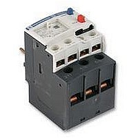
Description, characteristics Description 2 1 Setting dial Ir 2 Test button 3 Stop button 4 Reset button 5 Trip indication 6 Setting locked by sealing the cover 7 Class 10/class 20 selector 8 Selector for balanced load / unbalanced load ...

Page 4

Characteristics Electrical characteristics of power circuit Relay type Tripping class Conforming to UL 508, EN 60947-4-1 Rated insulation voltage (Ui) Conforming to EN 60947-4-1 Conforming to UL, CSA Rated impulse withstand voltage (Uimp) Frequency limits Of the operational current Setting ...

Page 5

References 2 LRD-08 LRD-21 2.3 LRD-33pp LRD-083 Characteristics: Dimensions: pages 2/108 to 2/111 pages 2/116 to 2/118 2/112 TeSys protection components 3-pole thermal overload relays, model d Differential thermal overload relays for use with fuses. Class 10 A tripping p ...

Page 6

References Differential thermal overload relays for use with fuses. Class 20 tripping p Compensated relays with manual or automatic reset, p with relay trip indicator, p for a.c. or d.c. p LR2-D1508 to 2553: independent mounting - either by ordering ...

Page 7

Schneider Electric ...

Page 8

References Accessories Description Pre-wiring kit allowing direct connection of the N/C contact of relay LRD-01…35 or LR3-D01…D35 to the contactor Terminal blocks (1) for clip-on mounting rail (AM1-DP200) or screw fixing; for fixing centres, see pages 2/116 ...

Page 9

Dimensions LRD-01...35 Direct mounting beneath contactors with screw clamp connections LC1- D09...D18 D25...D38 b 123 137 c see pages 2/94 and 2/95 LRD-3ppp 2.3 Direct mounting beneath contactors LC1-D40 to D95 and LP1-D40 to D80 109 4 ...

Page 10

Mounting LRD-01...35 Independent mounting centres or on rail AM1-DP200 or DE200 LAD-7B10 Remote tripping or electrical reset LAD-703 (1) 32 (1) Can only be mounted on RH side of relay LRD-01...35 LR2-D15pp Independent mounting ...

Page 11

Mounting (continued) LRD-3ppp and LR2-D35pp Independent mounting centres or on mounting rail AM1-DP200 or DE200 LA7-D3064 2 121 d 2xØ4,5 AM1-DP200 AM1-DE200 d 2 9.5 LR2-D and LRD-3ppp Adapter for door interlock mechanism 2.3 LA7-D1020 c 10 ...

Page 12

Schemes LRD, LR2-D and LR3-D Auto Reset Man. Test Stop LR9-D5ppp _ KM1 (3) (4) Test Stop Reset man LR9-D67 and LR9-D69 _ KM1 (3) (4) (5) Test Stop Reset man. ...

Related keywords