LRD04 TELEMECANIQUE, LRD04 Datasheet - Page 4
LRD04
Manufacturer Part Number
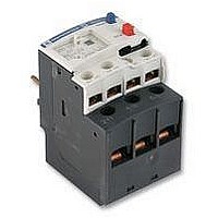
LRD04
Description
RELAY, OVERLOAD, 0.4-0.6A
Manufacturer
TELEMECANIQUE
Specifications of LRD04
Overload Adjustment Current Min
0.4A
Overload Adjustment Current Max
0.63A
Approval Bodies
CSA, UL
Contact Current Max
5A
External Depth
70mm
External Length / Height
51mm
External Width
45mm
Contact Form
1 NO, 1 NC
Current, Rating
0.63 A
Current, Rating Max
0.63
Function
Overload
Mounting Type
Clamp
Primary Type
Contactor
Relay Type
Electro Mechanical
Terminal Type
Screw
Termination
Screw
Voltage, Control
575 VAC


Relay type
Tripping class
Rated insulation voltage (Ui)
Rated impulse withstand
voltage (Uimp)
Frequency limits
Setting range
Power circuit connections
Temperature compensation
Tripping thresholds
Sensitivity to phase failure
Rated supply voltage
Supply voltage limits
Current consumption
Switching capacity
Protection
Voltage drop
Cabling
Tightening torque
Tripping curve LR9-D
Average operating time
related to multiples of the
current setting
(1) For use of these relays with soft start units or variable speed controllers, please call our Customer information centre on 0870 608 8 608.
Electrical characteristics of power circuit
Operating characteristics
Alarm circuit characteristics
Characteristics
References:
pages 2/112 and 2/113
Schneider Electric
Dimensions:
pages 2/116 to 2/118
1000
Tripping time in seconds
Conforming to UL 508, EN 60947-4-1
Conforming to EN 60947-4-1
Conforming to UL, CSA
Of the operational current
Depending on model
Width of terminal lug
Clamping screw
Tightening torque
To EN 60947-4-1
Conforming to EN 60947-4-1
d.c. supply
No load
Short-circuit and overload
Closed state
Flexible cable without cable end
100
10
1
0
1
1,12 2
Alarm
Tripping
3
4
TeSys protection components
3-pole electronic thermal overload relays LR9-D
1
2
Schemes:
page 2/119
5
6
V
V
kV
Hz
A
mm
N.m
˚C
A
A
V
V
mA
mA
V
mm
N.m
2
7
LR9-D
10 A or 20
1000
600
8
50…60. For other frequencies, call our Customer information centre on
0870 608 8 608 (1)
60…150
20
M8
18
- 20…+ 70
1.05 ± 0.06 In
1.12 ± 0.06 In
Tripping in 4 s ± 20 % in the event of phase failure
24
17…32
≤ 5
0…150
Self-protected
≤ 2.5
0.5…1.5
0.45
8
9
x the current setting (Ir)
10
11
12
1
2
Cold state curve
Hot state curve
2/111
2.3
2
Related parts for LRD04
Image
Part Number
Description
Manufacturer
Datasheet
Request
R

Part Number:
Description:
Control Contactor
Manufacturer:
TELEMECANIQUE
Datasheet:

Part Number:
Description:
Control Contactor
Manufacturer:
TELEMECANIQUE
Datasheet:

Part Number:
Description:
Contactor
Manufacturer:
TELEMECANIQUE
Datasheet:

Part Number:
Description:
Contactor
Manufacturer:
TELEMECANIQUE
Datasheet:
Part Number:
Description:
Control Contactor
Manufacturer:
TELEMECANIQUE
Datasheet:

Part Number:
Description:
CONTACTOR, 2NO/2NC, 9A, 230VAC
Manufacturer:
TELEMECANIQUE
Datasheet:

Part Number:
Description:
Contactor
Manufacturer:
TELEMECANIQUE
Datasheet:

Part Number:
Description:
CONTACTOR, 4KW, 400VAC
Manufacturer:
TELEMECANIQUE
Datasheet:

Part Number:
Description:
CONTACTOR, 5.5KW, 230VAC
Manufacturer:
TELEMECANIQUE
Datasheet:
Part Number:
Description:
CONTACTOR, 5.5KW, 400VAC
Manufacturer:
TELEMECANIQUE
Datasheet:

Part Number:
Description:
PILOT LIGHT HEAD, WHITE
Manufacturer:
TELEMECANIQUE
Datasheet:

Part Number:
Description:
LENS HEAD, BA 9S
Manufacturer:
TELEMECANIQUE
Datasheet:
Part Number:
Description:
LENS HEAD, BA 9S
Manufacturer:
TELEMECANIQUE
Datasheet:

Part Number:
Description:
LED BODY, 24V
Manufacturer:
TELEMECANIQUE
Datasheet:
Part Number:
Description:
LED BODY, 48V
Manufacturer:
TELEMECANIQUE
Datasheet: