10250T201NC2N EATON CUTLER HAMMER, 10250T201NC2N Datasheet - Page 233
10250T201NC2N
Manufacturer Part Number
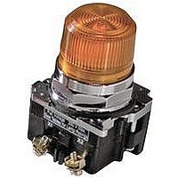
10250T201NC2N
Description
INDICATOR, INCAND LAMP, BAYONET
Manufacturer
EATON CUTLER HAMMER
Datasheet
1.10250T102.pdf
(320 pages)
Specifications of 10250T201NC2N
Base Type
Bayonet
Supply Voltage
120V
Current Rating
6A
Contact Current Max
6A
Illumination
Illuminated
Switch Features
Resistor
Actuator Style
Pushbutton
Color
Green
Lead Free Status / RoHS Status
Contains lead / RoHS non-compliant


Step 3: Cam Selection.
The cam you select
determines the operation of
all contact blocks mounted to
the operator. It is selected on
the basis that it provides the
simplest circuitry for the
desired “X-O” diagram. The
selection tables show all the
“X-O” combinations. For the
purpose of this example, the
applicable portion of those
tables is shown on this page.
Now to make the cam
selection, make a simple
worksheet such as:
X O O
O O X
It becomes immediately
obvious that cam 3 is the
better choice for two
reasons, (1) the series
combination can be avoided
making it simpler to wire,
(2) only two contacts are
required, which is less
expensive than the three
contacts required by cam 2.
Step 4: Contact Block
Selection.
Having selected the cam,
contact block selection is
simply a matter of gathering
the A position and B position
circuits into pairs which make
up the most convenient contact
block arrangement. If there is
an imbalance in the number of
circuits under A or B, then
single circuit blocks must be
selected for these leftover
circuits.
Back to the worksheet,
having selected cam 3 do
this:
X O X
O O X
ANO
(A)NO-(B)NC
Cam 2
(B)NO
BNO
10250T2
Cam 3
(A)NO
(B)NO
Step 5: Selector Switch
Operator.
Lastly, you have to choose
from the many types of
operators—knob and lever in
various colors or keyed. Also
what combinations of
maintained and spring return
functions are required.
Selection of these operators
can be found on Page 235.
For the example in step 4,
you may want a three-
position maintained black
knob, cam 3—Catalog
Number E34VHBK1.
The Complete Switch:
E34VHBK1 with one
10250T2 or, for one
composite catalog number,
E34VHBK1-Y1 found on
Page 232.
Diagrams
Circuits shown illustrate
connections to obtain a
selector switch circuit
combination and are shown
with their appropriate line
diagrams. Field wiring of
jumper connections required
as shown.
X = Closed circuit
O = Open circuit
Wiring of Jumper
Connections
Series Connection
Parallel Connection
Four-position selector
switches are limited to four
contact blocks.
Contact Blocks
For selection and number of
available contact blocks per
operator, see Page 244.
30.5 mm Corrosion Resistant Watertight/Oiltight—E34
Pushbuttons and Indicating Lights
Control Products Catalog CA08102001E—August 2010 www.eaton.com
Example Selection Table
No.
1
4
Two-Position Selector Switch Contact Block Selection
No.
1
2
Note
Wired in series.
“X-O” Pattern
X
O
Desired Circuit and
Operator Position
X
O
O
O
O
X
O
X
Cam Code #2
Top A
NO
—
Contact Blocks Required to
Accomplish Circuit Function
Top Plunger A
NC
NO
Bottom B
NO
NC
or
or
Cam Code #3
Top A
NO
—
Bottom Plunger B
NC
NO
47.7
Bottom B
—
NO
233
47
47
47
47
47
47
47
47
47
47
47
47
47
47
47
47
47
47
47
47
47
47
47
47
47
47
47
47
47
47
Related parts for 10250T201NC2N
Image
Part Number
Description
Manufacturer
Datasheet
Request
R

Part Number:
Description:
CONTACT BLOCK, 2NO, 6A, SCREW
Manufacturer:
EATON CUTLER HAMMER
Datasheet:

Part Number:
Description:
RECEPTACLE, MDR, R/A, 50WAY
Manufacturer:
3M
Datasheet:

Part Number:
Description:
RECEPTACLE, MDR, STRAIGHT, 50WAY
Manufacturer:
3M
Datasheet:

Part Number:
Description:
CONN MDR RECPT 50POS VERT T/H
Manufacturer:
3M
Datasheet:

Part Number:
Description:
CONN MDR RECEPT 50POS R/A SMD
Manufacturer:
3M
Datasheet:
Part Number:
Description:
CONN MDR RCPT 50POS R/A 4-40
Manufacturer:
3M
Datasheet:

Part Number:
Description:
CONN MDR RCPT 50POS R/A SMD 20AU
Manufacturer:
3M
Datasheet:

Part Number:
Description:
CONN MDR RECPT 50POS IDC GOLD
Manufacturer:
3M
Datasheet:


Part Number:
Description:
Handle Tie Bar For (2) - 1 Pole Type BR Breakers
Manufacturer:
EATON CUTLER HAMMER
Part Number:
Description:
Type CL Breaker 25A/1Pole 120/240V 10K-Classified 1" Ckt Bkr
Manufacturer:
EATON CUTLER HAMMER