10250T201NC2N EATON CUTLER HAMMER, 10250T201NC2N Datasheet - Page 299
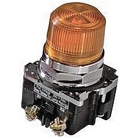
10250T201NC2N
Manufacturer Part Number
10250T201NC2N
Description
INDICATOR, INCAND LAMP, BAYONET
Manufacturer
EATON CUTLER HAMMER
Datasheet
1.10250T102.pdf
(320 pages)
Specifications of 10250T201NC2N
Base Type
Bayonet
Supply Voltage
120V
Current Rating
6A
Contact Current Max
6A
Illumination
Illuminated
Switch Features
Resistor
Actuator Style
Pushbutton
Color
Green
Lead Free Status / RoHS Status
Contains lead / RoHS non-compliant


Push-Pull Operators
An illuminated push-pull
pushbutton unit, arranged for
one-hole mounting, can
replace two pushbuttons and
a pilot light or the non-
illuminated form can replace
two pushbuttons. These units
are available in three basic
types:
●
●
10250T_
E34G_
Maintained—(Two-
position). Maintains in the
pulled or pushed position
until manually actuated to
the opposite mode.
Momentary—(Three-
position). Spring returns to
an intermediate position
when pulled or pushed and
released.
Push-Pull Operator Components
Type of Operator
Two-Position Operator without Lens
Maintained push-pull
Three-Position Operator without Lens
Momentary push-pull
Maintained push-momentary pull
Momentary push-pull
Note
Use NEMA 4X 10250T operators where exposed to ultraviolet light.
●
The operators, buttons,
contact blocks, etc., are
offered as building block
components that can be
intermixed to satisfy many
requirements. This minimizes
the need for a varied and
costly inventory.
Momentary Pull,
Maintained Push—(Three-
position). Spring returns to
intermediate position when
pulled. Maintains in pushed
position until manually
returned to intermediate
(ready to reset) position.
Maintained stop holds
circuit open and will
prevent other series
connected operators from
starting the system.
30.5 mm Class I Division 2 Hazardous Locations—10250T/E34
Contact
Block
1NO
1NC
2NO
2NC
1NO
1NC
2NO
2NC
1NO
1NC
2NO
2NC
Pushbuttons and Indicating Lights
Control Products Catalog CA08102001E—August 2010 www.eaton.com
Operator Position and Circuit Arrangement
Out—Pull
Contact Block Mounting Location
1
O
X
O
X
O
X
O
X
O
X
O
X
or
or
or
Application Guide
To assist in the selection of
contact blocks, the sketch
below shows pictorially by
symbols 1 and 2 locations of
contact circuits after
assembly of contact blocks
and adapter to the operator.
The table below shows the
effect of the push and pull
operations on either NO or
NC contacts. (X = contact
closed, O = contact open).
Locating Nibs
2
O
X
O
X
O
X
O
X
O
X
O
X
Intermediate
1
No intermediate
position
O
O
O
O
O
O
O
O
Locating Nib
or
or
2
O
X
O
X
O
O
O
O
1
In—Push
1
X
O
X
O
X
O
X
O
X
O
X
O
or
or
or
2
X
O
X
O
O
O
O
O
X
O
X
O
2
10250T
Catalog Number
10250T5
10250T4
10250T9
10250T10
E34
Catalog Number
E34GDB
E34GEB
E34GFB
E34GHB
47.9
299
47
47
47
47
47
47
47
47
47
47
47
47
47
47
47
47
47
47
47
47
47
47
47
47
47
47
47
47
47
47
Related parts for 10250T201NC2N
Image
Part Number
Description
Manufacturer
Datasheet
Request
R

Part Number:
Description:
CONTACT BLOCK, 2NO, 6A, SCREW
Manufacturer:
EATON CUTLER HAMMER
Datasheet:

Part Number:
Description:
RECEPTACLE, MDR, R/A, 50WAY
Manufacturer:
3M
Datasheet:

Part Number:
Description:
RECEPTACLE, MDR, STRAIGHT, 50WAY
Manufacturer:
3M
Datasheet:

Part Number:
Description:
CONN MDR RECPT 50POS VERT T/H
Manufacturer:
3M
Datasheet:

Part Number:
Description:
CONN MDR RECEPT 50POS R/A SMD
Manufacturer:
3M
Datasheet:
Part Number:
Description:
CONN MDR RCPT 50POS R/A 4-40
Manufacturer:
3M
Datasheet:

Part Number:
Description:
CONN MDR RCPT 50POS R/A SMD 20AU
Manufacturer:
3M
Datasheet:

Part Number:
Description:
CONN MDR RECPT 50POS IDC GOLD
Manufacturer:
3M
Datasheet:


Part Number:
Description:
Handle Tie Bar For (2) - 1 Pole Type BR Breakers
Manufacturer:
EATON CUTLER HAMMER
Part Number:
Description:
Type CL Breaker 25A/1Pole 120/240V 10K-Classified 1" Ckt Bkr
Manufacturer:
EATON CUTLER HAMMER