10250T201NC2N EATON CUTLER HAMMER, 10250T201NC2N Datasheet - Page 305
10250T201NC2N
Manufacturer Part Number
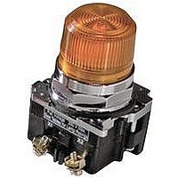
10250T201NC2N
Description
INDICATOR, INCAND LAMP, BAYONET
Manufacturer
EATON CUTLER HAMMER
Datasheet
1.10250T102.pdf
(320 pages)
Specifications of 10250T201NC2N
Base Type
Bayonet
Supply Voltage
120V
Current Rating
6A
Contact Current Max
6A
Illumination
Illuminated
Switch Features
Resistor
Actuator Style
Pushbutton
Color
Green
Lead Free Status / RoHS Status
Contains lead / RoHS non-compliant


Selector Switch Selection
10250T
Cam and Contact Block Selection
Selector switches in their
varied forms (two-position,
three-position, and four-
position) are a big factor
contributing to the great
flexibility of control that a well
rounded line of “pushbuttons”
can achieve. Because of their
flexibility, they tend to cause
difficulty with product
selection and application.
The following systematic
approach should simplify
that task.
Cam and contact block
selection is better understood
if you:
●
●
Work with each incoming
and outgoing wire/circuit
separately.
Recognize the terms NO
and NC only identify the
type of contact by its mode
before mounting to the
operator. The “X-O” table
(Page 307) shows how
that contact will act after
assembly to the operator
with the selected cam
shape. X = closed circuit,
O = open circuit.
E34
●
●
Contact Circuit Locations
One NO-NC contact block
may be mounted behind
each plunger of the
mounting adapter for a
total of four circuits.
Each cam has two
separate lobes, each of
which operates one of the
two contact block plungers
independently of each
other. Those are identified
as position 1 (locating nib
side) and position 2
(opposite of locating nib).
The position designations
give direction in selecting
and mounting of the
contact blocks.
Locating Nib
30.5 mm Class I Division 2 Hazardous Locations—10250T/E34
1
Pushbuttons and Indicating Lights
Control Products Catalog CA08102001E—August 2010 www.eaton.com
2
Systematic Approach
Application: HAND-OFF-
AUTO selector switch. In this
circuit, one incoming line is
distributed to two other
outgoing circuits by the
switch. The two circuits can
be looked at individually.
Step 1: Elementary
Diagram.
Construct on paper, or in your
mind, a simple elementary
diagram of the switching
scheme as follows:
Incoming
Step 2: “X-O” Pattern.
From the elementary
diagram, you can construct
an “X-O” diagram which
describes when the contacts
are to be closed (X) or open
(O) in the various positions of
the switch. The “X-O” for the
HAND circuit looks like this:
Line
HAND OFF AUTO
X O O
HAND
OFF
AUTO
Outgoing
Outgoing
Circuit
Circuit
In this circuit, you want a
contact closed on the left
(HAND) but open in the
center and right.
For the AUTO circuit, the “X-
O” diagram would look like
this:
Putting them together, the
complete “X-O” diagram is:
Once the “X-O” diagram has
been generated, the next
step is to select the cam and
contact block, or blocks,
needed to perform the
desired “X-O” functions. The
selection tables on the
following pages list the
various types (shapes) of
cams by number to choose
from and the type of contact
and position to achieve the
function outlined in your
“X-O” diagram.
HAND OFF AUTO
O O X
X O O
O O X
47.9
305
47
47
47
47
47
47
47
47
47
47
47
47
47
47
47
47
47
47
47
47
47
47
47
47
47
47
47
47
47
47
Related parts for 10250T201NC2N
Image
Part Number
Description
Manufacturer
Datasheet
Request
R

Part Number:
Description:
CONTACT BLOCK, 2NO, 6A, SCREW
Manufacturer:
EATON CUTLER HAMMER
Datasheet:

Part Number:
Description:
RECEPTACLE, MDR, R/A, 50WAY
Manufacturer:
3M
Datasheet:

Part Number:
Description:
RECEPTACLE, MDR, STRAIGHT, 50WAY
Manufacturer:
3M
Datasheet:

Part Number:
Description:
CONN MDR RECPT 50POS VERT T/H
Manufacturer:
3M
Datasheet:

Part Number:
Description:
CONN MDR RECEPT 50POS R/A SMD
Manufacturer:
3M
Datasheet:
Part Number:
Description:
CONN MDR RCPT 50POS R/A 4-40
Manufacturer:
3M
Datasheet:

Part Number:
Description:
CONN MDR RCPT 50POS R/A SMD 20AU
Manufacturer:
3M
Datasheet:

Part Number:
Description:
CONN MDR RECPT 50POS IDC GOLD
Manufacturer:
3M
Datasheet:


Part Number:
Description:
Handle Tie Bar For (2) - 1 Pole Type BR Breakers
Manufacturer:
EATON CUTLER HAMMER
Part Number:
Description:
Type CL Breaker 25A/1Pole 120/240V 10K-Classified 1" Ckt Bkr
Manufacturer:
EATON CUTLER HAMMER