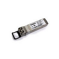
AFBR-703SDDZ Avago Technologies US Inc., AFBR-703SDDZ Datasheet - Page 2

AFBR-703SDDZ
Manufacturer Part Number
AFBR-703SDDZ
Description
SFP+ 850nm 1/10GbE SR MMF,Gen2 STD
Manufacturer
Avago Technologies US Inc.
Series
-r
Datasheet
1.AFBR-703SDDZ.pdf
(22 pages)
Specifications of AFBR-703SDDZ
Data Rate
10.312Gbd
Wavelength
850nm
Applications
Ethernet
Voltage - Supply
3.135 V ~ 3.465 V
Connector Type
LC Duplex
Mounting Type
SFP+
Optical Fiber Type
TX/RX
Data Transfer Rate
10313MBd
Optical Rise Time
0.028ns
Optical Fall Time
0.028ns
Operating Temperature Classification
Commercial
Peak Wavelength
860nm
Package Type
SFP
Operating Supply Voltage (min)
3.135V
Operating Supply Voltage (typ)
3.3V
Operating Supply Voltage (max)
3.465V
Output Current
20mA
Operating Temp Range
0C to 70C
Mounting
Snap Fit To Panel
Pin Count
20
Lead Free Status / RoHS Status
Lead free / RoHS Compliant
Lead Free Status / RoHS Status
Lead free / RoHS Compliant
Description,
Installation
The AFBR-703SDDZ transceiver package is compli-
ant with the SFF 8432 Improved Pluggable Formfactor
housing specification for the SFP+. It can be installed in
any INF-8074 or SFF-8431/2 compliant Small Form Plug-
gable (SFP) port regardless of host equipment operating
status The AFBR-703SDDZ is hot-pluggable, allowing the
module to be installed while the host system is operat-
ing and on-line. Upon insertion, the transceiver housing
makes initial contact with the host board SFP cage, miti-
gating potential damage due to Electro-Static Discharge
(ESD).
By selecting TX rate select to 1.25 Gbps operation, the
module TX performance complies with the extinction
ratio and output power level in 1000BASE-SX specifica-
tions.
Likewise RX performance complies with the sensitivity
performance in the 1000BASE-SX specifications by se-
lecting RX rate select to 1.25 Gbps operation.
The rate select can be done through either the hardware
pins or the software access to the A2h page of EEPROM
map. The user can refer to the Appendix for details of
rate select.
Digital Diagnostic Interface and Serial Identification
The two-wire interface protocol and signaling detail are
based on SFF-8431. Conventional EEPROM memory,
bytes 0-255 at memory address 0xA0, is organized in
compliance with SFF-8431. New digital diagnostic in-
formation, bytes 0-255 at memory address 0xA2, is
compliant to SFF-8472. The new diagnostic information
provides the opportunity for Predictive Failure Identifi-
cation, Compliance Prediction, Fault Isolation and Com-
ponent Monitoring.
Predictive Failure Identification
The AFBR-703SDDZ predictive failure feature allows a
host to identify potential link problems before system
performance is impacted. Prior identification of link
problems enables a host to service an application via
“fail over” to a redundant link or replace a suspect device,
maintaining system uptime in the process. For applica-
tions where ultra-high system uptime is required, a
digital SFP provides a means to monitor two real-time
laser metrics asso ciated with laser degradation and pre-
dicting failure: average laser bias current (Tx_Bias) and
average laser optical power (Tx_Power).
2
continued
Compliance Prediction
Compliance prediction is the ability to determine if an
optical transceiver is operating within its operating and
environmental requirements. AFBR-703SDDZ devices
provide real-time access to transceiver internal supply
voltage and temperature, allowing a host to identify po-
tential component compliance issues. Received optical
power is also available to assess compliance of a cable
plant and remote transmitter. When operating out of
requirements, the link cannot guarantee error free trans-
mission.
Fault Isolation
The fault isolation feature allows a host to quickly pin-
point the location of a link failure, minimizing downtime.
For optical links, the ability to identify a fault at a local
device, remote device or cable plant is crucial to speed-
ing service of an installation. AFBR-703SDDZ real-time
monitors of Tx_Bias, Tx_Power, Vcc, Temperature and Rx_
Power can be used to assess local transceiver current op-
erating conditions. In addition, status flags TX_DISABLE
and Rx Loss of Signal (LOS) are mirrored in memory and
available via the two-wire serial interface.
Component Monitoring
Component evaluation is a more casual use of the
AFBR-703SDDZ real-time monitors of Tx_Bias, Tx_Power,
Vcc, Temperature and Rx_Power. Potential uses are as
debugging aids for system installation and design, and
transceiver parametric evaluation for factory or field
qualification. For example, temperature per module can
be observed in high density applications to facilitate
thermal evaluation of blades, PCI cards and systems.


