FM-RX1-433A RF Solutions, FM-RX1-433A Datasheet - Page 2
FM-RX1-433A
Manufacturer Part Number
FM-RX1-433A
Description
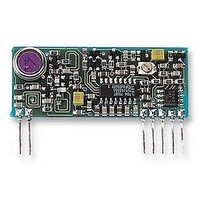
MODULE, RECEIVER, FM
Manufacturer
RF Solutions
Datasheet
1.FM-RX1-433A.pdf
(7 pages)
Specifications of FM-RX1-433A
Svhc
No SVHC (15-Dec-2010)
Current Rating
14mA
Data Rate Max
10000bps
Frequency
433MHz
Operating Distance
300m
Operating Temperature Max
55°C
Operating Temperature Min
-10°C
Safety Category
DTI MPT1340


DS000021
PIN DESCRIPTION
This receiver module is a double conversion FM Superhet with a data slicer driven by the AF output. Additionally,
a fast acting carrier detect signal is a available to indicate to external circuits that a signal is present. This signal
is extremely useful when implementing duty cycle power save circuits or to indicate to external logic that a signal
is being received. It is internally derived from the degree of noise quieting due to the presence of a received
carrier.
The receiver is designed to work with the matching transmitter (FMTX). With the addition of simple antenna the
pair may be used to transfer serial data up to 200 metres. The range of the system depends upon several factors,
principally the type of antenna employed and the operating environment. The 200m quoted range is a reliable
operating distance over open ground using 1/4 whip antenna at both ends of the link at 1.5 metres above ground.
Smaller antenna, interference or obstacles (e.g. buildings) will reduce the reliable working range (down to 30
metres in extreme cases). Increased antenna height, slow data or a larger receive antenna will increase the
range.
Warning - Don’t be tempted to adjust the trimmer on the module, it controls the receive frequency and can only
be correctly set-up with an accurate RF signal generator.
FUNCTIONAL DESCRIPTION
MODULE MOUNTING CONSIDERATIONS
Pin No
1. The module may be mounted vertically or bent horizontal to the motherboard.
2. No conductive items should be placed within 4mm of the module’s component side, to prevent detuning.
3. Observe RF layout practice between the module and it’s antenna, i.e <10mm unscreened track, use 50
4. It is good practice to earth plane all unused area around the module.
5. Mount as far as possible from high frequency interference sources. Microprocessors with external busses
6. In some applications it is advantageous to locate the receiver and it’s antenna away from the main
1
2
3
4
5
6
7
Rev 2.1
microstrip or coax for >10mm.
are especially incompatible with sensitive radio receivers and should be kept at least 1 metre from the
receive antenna. Single chip microcontrollers are much less of a problem.
equipment. This avoids interference problems and allows for flexibility in the sitting of the receive antenna
for optimum RF performance.
R.F. IN
R.F. GND
DETECT
0 VOLT
Vcc
AF
DATA
Jul ‘99
Name
FM R. F. R
Connects to the Receiver antenna. Has nominal 50
isolated from internal circuit.
Should be connected to any ground plane against which the antenna works.
(Internally connected to pin 4).
May be used to derive a carrier detect to enable external circuit when a signal is
being received. If the detect function is unused connect a 10k
5).
Ground for Supply.
Supply Voltage. Note; Must be a clean supply (<2mV pk-pk ac), stable and free of
high frequency digital noise. A supply filter is recommended unless the module is
driven from its own regulated supply.
FM Demodulator output. It has a standing DC bias of approx. 2 volts and may be
used to drive analogue data detectors such as modem IC’s or DTMF decoders. Can
drive load impedances down to 2k
Digital output from the internal data slicer (true data as fed to the Transmitter’s Data
input). Output is a squared version of the AF signal (pin 6). This signal is used to
drive external digital decoders. Can drive load impedances down to 1k
1nF.
1999 REG No 277 4001, ENGLAND.
ECEIVER
M
ODULES
and up to 100pF.
Description
.
impedance and is capacitively
FMRX1- XXXX
resistor to Vcc (pin
Page 2
and up to
Related parts for FM-RX1-433A
Image
Part Number
Description
Manufacturer
Datasheet
Request
R

Part Number:
Description:
RECEIVER, HYBRID, FM
Manufacturer:
TELECONTROLLI
Datasheet:
Part Number:
Description:
TRANSMITTER, HYBRID, FM
Manufacturer:
TELECONTROLLI
Datasheet:

Part Number:
Description:
RECEIVER, FM
Manufacturer:
RF Solutions
Datasheet:

Part Number:
Description:
MODULE, TRANSMITTER, FM
Manufacturer:
RF Solutions
Datasheet:
Part Number:
Description:
FM / Fmx-r Stereo Decoders
Manufacturer:
ETC
Datasheet:

Part Number:
Description:
IC ENCODER TRANSMITTER RF 8DIP
Manufacturer:
RF Solutions
Datasheet:

Part Number:
Description:
IC DECODER RECEIVER RF 18DIP
Manufacturer:
RF Solutions
Datasheet:

Part Number:
Description:
IC ENCODER 3 DGTL I/O SOT23-6
Manufacturer:
RF Solutions
Datasheet:

Part Number:
Description:
IC ENCODER 3 DGTL I/O 8-PDIP
Manufacturer:
RF Solutions
Datasheet:

Part Number:
Description:
IC DECODER 3 DGTL I/O 8-PDIP
Manufacturer:
RF Solutions
Datasheet:

Part Number:
Description:
IC DECODER 3 DGTL I/O 8-SOIC
Manufacturer:
RF Solutions
Datasheet:
Part Number:
Description:
118 SERIES AM REMOTE CONTROL SYSTEMS.
Manufacturer:
RF Solutions Ltd.