LM5118EVAL National Semiconductor, LM5118EVAL Datasheet - Page 2
LM5118EVAL
Manufacturer Part Number
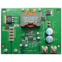
LM5118EVAL
Description
Buck-Boost Controller Eval. Board
Manufacturer
National Semiconductor
Datasheet
1.LM5118EVALNOPB.pdf
(10 pages)
Specifications of LM5118EVAL
Silicon Manufacturer
National
Application Sub Type
Buck/Boost Controller
Kit Application Type
Power Management - Voltage Regulator
Silicon Core Number
LM5118


www.national.com
Figure 2 illustrates the efficiency of the converter vs. input
voltage and output current. These curves highlight the high
efficiency of the converter, especially considering the simplic-
ity of design offered by a non synchronous implementation.
Note the discontinuity in the curves at approximately 17V and
13V which represent mode transition boundaries. The lower
efficiencies in the buck-boost region reflect additional losses
at higher input and inductor currents. The decrease in effi-
ciency at higher input voltages represents higher switching
losses.
The performance of the evaluation board is as follows:
Input Range: 75V to less than 5V at full current
Operation to 3V at reduced current and appropriate adjust-
ments*
Output Voltage: 12V
Output Current: 0 to 3A
Frequency of Operation: 300 kHz
Board Size: 3.45 X 2.65 inches
Load Regulation: 1%
Line Regulation: .1%
Over-Current Limiting
Operation with VIN greater or less than Vout
*Operation at full current to around 3V is possible with current
limit sense resistor, UVLO threshold, and corresponding
C
quired. See the datasheet and quick start for more details.
Air Flow
Prolonged operation without airflow at low input voltage and
at at full power will cause the MOSFET’s and Diodes to over-
heat. A fan with a minimum of 200 LFM should always be
provided. Figure 2 illustrates the temperature rise of various
components with no airflow. The ambient was 25°C, and VIN
was 8V.
ramp
adjustment. Additional input capacitance may be re-
FIGURE 2. Efficiency
30057502
2
FIGURE 3. Temperature vs Load Current with No Airflow
Powering Up
Connecting the IC’s enable pin to ground will allow powering
up the source supply with a minimal output load. Set the cur-
rent limit of the source supply to provide about 1.5 times the
anticipated wattage of the load. Note that input currents be-
come very high at low input voltages, which requires an
appropriate input supply. As you remove the connection from
the enable pin to ground, immediately check for 12 volts at
the output.
A quick efficiency check is the best way to confirm that ev-
erything is operating properly. If something is amiss, you can
be reasonable sure that it will affect the efficiency adversely.
Few parameters can be incorrect in a switching power supply
without creating losses and potentially damaging heat.
Over Current Protection
The evaluation board is configured with over-current protec-
tion. The output current is limited to approximately 4.5 amps
in the buck-boost mode The 4.5A value allows for component
tolerances to guarantee a 3A output current. Note this current
will be almost double, or about 7 amps in buck mode (Vin
greater than 17 volts) due to the difference in peak inductor
currents in the two different modes. However, a hard short will
trigger the hiccup mode of current limit as illustrated in Figure
4. In this mode, the average output current will be less than .
2 amps.
– 25°C Ambient
30057503
Related parts for LM5118EVAL
Image
Part Number
Description
Manufacturer
Datasheet
Request
R

Part Number:
Description:
National Semiconductor [8-Bit D/A Converter]
Manufacturer:
National Semiconductor
Datasheet:
Part Number:
Description:
National Semiconductor [Media Coprocessor]
Manufacturer:
National Semiconductor
Datasheet:
Part Number:
Description:
Digitally Controlled Tone and Volume Circuit with Stereo Audio Power Amplifier, Microphone Preamp Stage and National 3D Sound
Manufacturer:
National Semiconductor
Datasheet:
Part Number:
Description:
Digitally Controlled Tone and Volume Circuit with Stereo Audio Power Amplifier, Microphone Preamp Stage and National 3D Sound
Manufacturer:
National Semiconductor
Datasheet:
Part Number:
Description:
AC97 Rev 2 Codec with Sample Rate Conversion and National 3D Sound
Manufacturer:
National Semiconductor
Part Number:
Description:
Manufacturer:
National Semiconductor
Datasheet:
Part Number:
Description:
Manufacturer:
National Semiconductor
Datasheet:
Part Number:
Description:
General Purpose, Low Voltage, Low Power, Rail-to-Rail Output Operational Amplifiers
Manufacturer:
National Semiconductor
Datasheet:
Part Number:
Description:
8-bit 20 MSPS flash A/D converter.
Manufacturer:
National Semiconductor
Datasheet:
Part Number:
Description:
Low Noise Quad Operational Amplifier
Manufacturer:
National Semiconductor
Datasheet:
Part Number:
Description:
Quad Differential Line Receivers
Manufacturer:
National Semiconductor
Datasheet:
Part Number:
Description:
Quad High Speed Trapezoidal? Bus Transceiver
Manufacturer:
National Semiconductor
Datasheet:
Part Number:
Description:
Dual Line Receiver
Manufacturer:
National Semiconductor
Datasheet:
Part Number:
Description:
TTL to 10k ECL Level Translator with Latch
Manufacturer:
National Semiconductor
Datasheet: