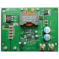
LM5118EVAL National Semiconductor, LM5118EVAL Datasheet - Page 3

LM5118EVAL
Manufacturer Part Number
LM5118EVAL
Description
Buck-Boost Controller Eval. Board
Manufacturer
National Semiconductor
Datasheet
1.LM5118EVALNOPB.pdf
(10 pages)
Specifications of LM5118EVAL
Silicon Manufacturer
National
Application Sub Type
Buck/Boost Controller
Kit Application Type
Power Management - Voltage Regulator
Silicon Core Number
LM5118
VCCX
A place for a jumper between VOUT and VCCX is provided
on the PC board. If operation below about 6 volts is required,
connect the jumper to allow VCCX to power the converter (the
exact voltage depends on the gate drive requirements of the
switching FETs). The converter does require a minimum VIN
of 5V to initially start. When running, the input voltage can
decrease to below 5V at reduced current with VCCX con-
nected to VOUT. Note that this design uses a current limit
value to guarantee a full 3A of output current at a minimum
VIN of 5V. For operation lower than 5V, the current limit re-
sistor, UVLO threshold, and ramp capacitor must be re-cal-
culated. Caution: make sure the input supply can source the
required input current. Operation at low VIN at full power may
overheat and damage the MOSFET’s and Diodes supplied on
the board. Note there is a limit of 14 volts applied to VCCX.
Never exceed this value if operating VCCX from an external
source, or operating the board with Vout greater than 12 volts.
To prevent oscillation, connect and additional 100uF or
FIGURE 4. Short Circuit Current
30057504
3
greater electrolytic capacitor across Vin for input voltages less
than 5 volts.
Mode Transition
With Vout set at 12 volts, the LM5118 applications board will
operate in the buck mode with VIN greater than about17 volts.
As VIN is reduced below 17 volts, the converter begins to op-
erate in a soft buck-boost mode. As VIN is decreased below
14 volts, the converter smoothly transitions to a pure buck-
boost mode. This method of mode transition insures a
smooth, glitch free operation as VIN is varied over the transi-
tion region.
Figure 5 illustrates soft mode transition. The boost switch
pulse-width is relatively narrow compared to the buck switch
waveform. The boost switch pulse-width will gradually in-
crease as VIN decreases, and will eventually match and lock
to the buck switch waveform. At this point, the converter en-
ters full buck-boost operation.
FIGURE 5. Mode Transition
30057505
www.national.com


