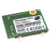
Q2686H WAVECOM, Q2686H Datasheet - Page 64

Q2686H
Manufacturer Part Number
Q2686H
Description
MODULE, GSM/GPRS, QUAD BAND
Manufacturer
WAVECOM
Datasheet
1.Q2686H.pdf
(89 pages)
Specifications of Q2686H
Mcu Supported Families
ARM9
Kit Features
GSM/GPRS Class 10 Quad Band Version, 32MB Of Bursted Flash Memory, 8MB Of SRAM
Tool / Board Applications
Wireless Communication
Development Tool Type
CPU
Lead Free Status / RoHS Status
Lead free / RoHS Compliant
- Current page: 64 of 89
- Download datasheet (2Mb)
3.21
Digital audio interface (PCM) interface mode allows connectivity with audio
standard peripherals. It can be used, for example, to connect an external audio
codec.
The programmability of this mode allows to address a large range of audio
peripherals.
PCM features:
The digital audio interface configuration cannot differ from that specified
above.
3.21.1 Description
The PCM interface consists of 4 wires:
This document is the sole and exclusive property of WAVECOM. Not to be distributed or divulged without
prior written agreement.
WM_PRJ_Q2686_PTS_001-007
•
•
•
•
•
•
•
•
•
•
•
IOM-2 compatible device on physical level
Master mode only with 6 slots by frame, user only on slot 0
Bit rate single clock mode at 768KHz only
16 bits data word MSB first only
Linear Law only (no compression law)
Long Frame Synchronization only
Push-pull configuration on PCM-OUT and PCM-IN
PCM-SYNC (output): The frame synchronization signal delivers an 8KHz
frequency pulse that synchronizes the frame data in and the frame data
out.
PCM-CLK (output): The frame bit clock signal controls data transfer with
the audio peripheral.
PCM-OUT (output): The frame “data out” relies on the selected
configuration mode.
PCM-IN (input): The frame “data in” relies on the selected configuration
mode.
Digital Audio Interface (PCM)
confidential ©
Q2686 Wireless CPU
Interfaces
March 6, 2007
Page: 63 / 87
®
Related parts for Q2686H
Image
Part Number
Description
Manufacturer
Datasheet
Request
R

Part Number:
Description:
KIT. DEV, Q2686H, GSM/GPRS
Manufacturer:
WAVECOM
Datasheet:


