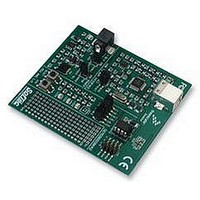
RS08KA2 PROMO Freescale Semiconductor, RS08KA2 PROMO Datasheet - Page 20

RS08KA2 PROMO
Manufacturer Part Number
RS08KA2 PROMO
Description
DEMO KIT, SILICON BUNDLE, RS08KA2
Manufacturer
Freescale Semiconductor
Datasheet
1.RS08KA2_PROMO.pdf
(34 pages)
Specifications of RS08KA2 PROMO
Kit Contents
DEMO9RS08KA2 Board, USB Cable, Quick Start Guide, User Manual, Packing List
Svhc
No SVHC (15-Dec-2010)
Development Tool Type
Demonstration Kit
Kit Features
RS08KA2 Microcontroller,
Silicon Manufacturer
Freescale
Core Architecture
RS08
Core Sub-architecture
RS08
Silicon Core Number
MC9RS08
Silicon Family Name
RS08KA
Rohs Compliant
Yes
Lead Free Status / RoHS Status
Lead free / RoHS Compliant
Introduction to RS08
be enabled when the corresponding interrupt enable bit is set. When the MCU wakes up from wait/stop
mode, the program flow is resumed from where it was stopped. At this point, software can determine
which interrupt had occurred by polling the interrupt flags and then jump to the service subroutine
accordingly.
The interrupt flags from individual modules are scattered in several register locations, therefore it is not
efficient for the software to poll the corresponding flag among several registers. The RS08 platform
implements a system interrupt pending (SIP1) register where it provides a central location for the interrupt
sources notification. If hardware interrupt is enabled, the corresponding flag in SIP1 register will be set
when the interrupt event occurs. For example, if keyboard interrupt is required, it can be enabled by setting
the KBIE bit in KBISC register. When KBI event occurs, KBF flag in KBISC register and KBI flag in SIP1
register are both set. User has a choice to poll either of these bits to determine of the event existence.
Writing a logic 1 to KBACK bit in KBISC register will clear both KBF in KBISC and KBI flag in SIP1.
1.8.1
The interrupt sources associated with the MC9RS08KA2 are shown below:
First, the priority of servicing should be defined based on the application need. In general, the interrupt
that requires the shortest latency should have the highest priority. To illustrate the idea the servicing
priority is arbitrarily defined as follows:
For many interrupt driven applications the interrupt event period is unknown to the application; most of
the time the MCU is in idle state and waiting for an event to trigger. Once it happens, the MCU will wakeup
and performs a defined task then returns to its idle state. With the priority table defined in
interrupt servicing loop can be written as follows:
InfLoop:
Priority1:
Priority2:
Priority3:
Priority4:
Priority5:
MTIM_ISR:
20
•
•
•
•
•
Low voltage detect (LVD)
Real timer interrupt (RTI)
Modulo timer overflow (MTIM)
Analog comparator (ACMP)
Keyboard interrupt (KBI)
Interrupt Handling Coding Example
Highest
sta
wait
brset
brset
brset
brset
brset
bra
;... <ISR coding> ...
MTIM
SRS
SIP1_MTIM, SIP1, MTIM_ISR
SIP1_ACMP, SIP1, ACMP_ISR
SIP1_KBI, SIP1, KBI_ISR
SIP1_RTI, SIP1, RTI_ISR
SIP1_LVD, SIP1, LVD_ISR
InfLoop
Table 1-5. Interrupt Servicing Priority Example
KBI
Getting Started with RS08, Rev. 1
ACMP
RTI
;Bump COP
;5 bus cycles
;5 bus cycles
;5 bus cycles
;5 bus cycles
;5 bus cycles
Lowest
LVD
Freescale Semiconductor
Table
1-5, the


