SK-XC164CM EASY KIT Infineon Technologies, SK-XC164CM EASY KIT Datasheet
SK-XC164CM EASY KIT
Specifications of SK-XC164CM EASY KIT


Related parts for SK-XC164CM EASY KIT

SK-XC164CM EASY KIT Summary of contents
Page 1
XC 164CM se ries Bo ard M anual, V.1.0, Jan. 2006 ...
Page 2
XC164CM series Easy Kit Revision History: Previous Version: Page Subjects (major changes since last revision) We Listen to Your Comments Any information within this document that you feel is wrong, unclear or missing at all? Your feedback will help us ...
Page 3
Table of Contents 1 Introduction . . . . . . . . . . . . . . . . . . . . . . . . . . . . . . . . . . . ...
Page 4
XC164CM series Board Manual XC164CM Board 4 XC164CM V 1.0, 2006-01 ...
Page 5
... MEMTOOL. The Evaluation Board allows easily the development of XC164CM family applications with the corresponding tools. Subsequently, the applications can be downloaded and can be tested with the powerful debugger software. For detailed technical information about the XC164CM please refer to the User´s Manual of the XC164CM V1 ...
Page 6
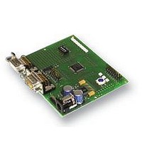
Features of the XC164CM series Easy Kit Board The XC164CM series Easy Kit is soldert with the XC164CM-8F device. This device fit into all members of this product family so that there are no special Easy Kit Boards necessary. ...
Page 7
Block Diagram Figure 1 Block diagram of XC164CM Easy Kit XC164CM series Board Manual Features of the XC164CM series Easy Kit Board T ...
Page 8
Layout Overview RS232 Figure 2 Top view Figure 3 Bottom view XC164CM series Board Manual Features of the XC164CM series Easy Kit Board Config 1 4 Infineon XC164CM CAN2 1 CAN1 8 XC164CM XC164CM Board 1 OCDS1 Reset 1 ...
Page 9
DIP Switch S102 Although most of the programmable features of the XC164CM are selected by software either during the initialization phase or repeatedly during program execution, some features must be selected earlier because they are used for the first ...
Page 10
Power Supply The XC164CM Board needs an external power supply. A regulated DC power supply with max. 12 Volts / 400mA can be connected to the power connector. Figure 4 Power Supply XC164CM series Board Manual Features of the ...
Page 11
Description of Connectors and Switches The On-Chip Bootstrap Loader allows the start code to be moved into the internal PSRAM of the XC164CM via the serial interface ASC0. The XC164CM will then execute the loaded start code out of ...
Page 12
Headers and Connectors 3.2.1 RS-232 Connector - ASC0 (P101) 3.2.2 CAN1 (P102) 3.2.3 CAN2 (X103) XC164CM series Board Manual Description of Connectors and Switches RxD0 TxD0 GND CAN1L GND 1 ...
Page 13
LIN Header (X104) 3.2.5 OCDS Interface On-board header X501 XC164CM series Board Manual Description of Connectors and Switches ...
Page 14
Power Headers (optional) The power headers can be mounted if a power inverter board for electrical motor drive application is used. BUX101 P1L.0 P1L.1 P1L.2 P1L.3 P1L.4 P1L.5 P1L.7 P1L.6 XC164CM series Board Manual Description of Connectors and Switches ...
Page 15
Pin Definition and Location P1H.0/C6P0/CC23/EX0IN P1H.1/C6P1/MRST1/EX1IN P1H.2/C6P2/MTSR1/EX2IN P1H.3/T7IN/SCLK1/EX3IN/E*) P1H.4/CC24/EX4IN P1H.5/CC25/EX5IN V SSP V DDP P5.0/AN0 P5.1/AN1 P5.2/AN2 P5.3/AN3 P5.4/AN4 P5.5/AN5 P5.10/AN10/T6EUD P5.11/AN11/T5EUD Figure 5 Pinout of the XC164CM XC164CM series Board Manual Description of Connectors and Switches 1 2 ...
Page 16
X108 Figure 6 Pin connector of the XC164CM Easy Kit XC164CM series Board Manual Description of Connectors and Switches Infineon XC164CM XC164CM XC164CM Board X106 V 1.0, 2006-01 ...
Page 17
Zero Ohm Resistors For configuration purposes several zero ohm resistors have been implemented. The functionality of these resistors are shown in the table below. Zero Ohm Resistors Table 4 Component TLE 6259-26 (LIN Transceiver Board Rev V2.0) TLE 7259 ...
Page 18
... The On-chip programming can be done either with a utility program, so called “Memtool” or with several other Toolchains of our Tool vendors. Memtool is using the ASC bootstrap Loader. The latest version can be found on the Infineon web side. Other tools are using the OCDS interface. ...
Page 19
Internal PRAM The XC164CM provides 2 Kbytes of PSRAM (E0’0000H … E0’07FFH). The PSRAM provides fast code execution without initial delays. Therefore, it supports non-sequential code execution, for example via the interrupt vector table. Figure 8 Memory mapping for ...
Page 20
Quick Start Up For a successful start up of the XC164CMEasy Kit the following items should be done: Start the index.htm on the EasyKit CD and follow the Getting Started. 5.1 Power Supply A regulated DC power supply with ...
Page 21
OCDS debugging interface The XC164CM includes an On-Chip Debug Support (OCDS) system, which provides convenient debugging, controlled directly by an external device via debug interface pins. Within the XC164CM Easy Kit you get the USB Wiggler. For installing all ...
Page 22
... Memtool is one of Infineon’s solutions for programming code and data into FLASH Memory. Memtool supports on-chip FLASH Memory as well as dedicated Flash chips on the target board. Memtool uses the ASC bootstrap Loader and can be found on the XC164CM Starterkit CD under Tools. 5.5 ASC-Bootstrap To establish the connection between the ASC bootstrap loader of the XC164CM microcontroller and the PC (MemTool) the bootstrap loader mode has to be configured ...
Page 23
Connect to the Target Make sure that the Starter Kit board is connected to your PC as well as to your power supply. Hit the reset key on the starter kit. Now press the 'connect' button in Memtool. If ...
Page 24
Program Press the “Program” Button and check the result of the programming. Figure 16 Program After the successful program press “Disconnect Now” 5.10 Execution Mode After the code is programmed in the internal flash the microcontroller has to be ...
Page 25
Schematic SLUG HEAT HS GND 11 GND 6 2 XC164CM series Board Manual P9.5 P9.4 T2EUD / AN15 / P5.15 T4EUD / AN14 / P5.14 VDDP T5IN / AN13 / P5.13 57 VDDP T6IN / AN12 ...
Page 26
XC164CM series Board Manual 26 XC164CM XC164CM Board Schematic V 1.0, 2006-01 ...
Page 27
... Infineon Technologies Office. Infineon Technologies Components may only be used in life-support devices or systems with the express written approval of Infineon Technologies. Life support devices or systems are intended to be implanted in the human body support and/or maintain and sustain and/or protect human life. If they fail reasonable to assume that the health of the user or other persons may be endangered ...
Page 28
Infineon goes for Business Excellence “Business excellence means intelligent approaches and clearly defined processes, which are both constantly under review and ultimately lead to good operating results. Better operating results and business excellence mean less idleness and wastefulness for all ...