26231941 Crouzet USA, 26231941 Datasheet - Page 18
26231941
Manufacturer Part Number
26231941
Description
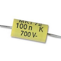
CAPACITOR, MOTOR MEDIUM TORQUE CAPACITOR, MOTOR MEDIUM TORQUE
Manufacturer
Crouzet USA
Datasheet
1.26231909.pdf
(196 pages)
Specifications of 26231941
Capacitance
0.1UF
Voltage Rating, Dc
700V
Capacitor Dielectric Type
POLYPROPYLENE
Tolerance,
10%
Tolerance, -
10%
Temp, Op. Max
85(DEGREE C)
Temp, Op. Min
0(DEGREE


1
18
Many applications call for a high start-up torque. The D.C. motor, by its
very nature, has a high torque vs. falling speed characteristic and this
enables it to deal with high starting torques and to absorb sudden rises in
load easily. The speed of the motor adjusts to the load. Furthermore, the
D.C. motor is an ideal way of achieving the miniaturisation designers are
constantly seeking because the efficiency it gives is high compared with
other designs.
➜ Safety
Crouzet D.C. motors are designed and manufactured for integration into
equipment or machines which meet, for example, the requirements of the
machinery standard :
EN 60335-1 (IEC 335-1, “Safety of domestic electrical appliances”).
Integration of Crouzet D.C. motors into equipment or machines should, as
a rule, take the following motor characteristics into account :
EC LOW VOLTAGE DIRECTIVE 73/23/EEC OF 19/02/73 :
Crouzet D.C. motors and geared motors are not covered by this directive
(LVD 73/23/EEC applies to voltages greater than 75 VDC).
➜ Electromagnetic compatibility (EMC)
Crouzet Ltd can provide the EMC characteristics of the various types of
product on request.
EC DIRECTIVE 89/336/EEC OF 03/05/89,
“ELECTROMAGNETIC COMPATIBILITY” :
D.C. motors and geared motors are considered as components meant
for integration into other equipment and therefore fall outside its field of
application. However, these products are designed in compliance with
EMC characteristics and consequently can be incorporated in equipment
having to comply with the EMC directive.
The motor unit is selected according to the required output power.
Depending on the required speed, a direct motor or a geared motor is
selected.
Speeds 1,000 to 5,000 rpm
Speeds below 500 rpm
The gearbox is selected depending on the maximum required torque and
the duty cycle.
This motor follows linear laws of operation and because of this it is
easier to fully exploit its characteristics compared to synchronous or
asynchronous motors.
Some principles of direct current (D.C.) motors
Why choose a D.C. motor ?
Design of Crouzet D.C. motors
How to select from the Crouzet range
Definition of the D.C. motor
■
■
■
■
no ground connection
so-called «principal insulation» motors (single insulation)
protection index : IP00 to IP40
insulation classes : A to F
Direct motor
Geared motor
}
(see the catalogue page
details for individual motor
types)
➜ Composition of a D.C. motor
The stator is formed by a metal carcass and one or more magnets
that create a permanent magnetic field inside the stator. At the rear of
the stator are the brush mountings and the brush gear which provide
electrical contact with the rotor.
The rotor is itself formed by a metal carcass carrying coils which are
interconnected at the commutator at the rear of the rotor.
The commutator and brush assembly then select the coil through which
the electric current passes in the opposite direction.
Principle of operation
Whatever the complexity of the rotor coil windings, once they are
energised, they may be represented in the form of a ferromagnetic
cylinder with a solenoid wrapped around it.
The wire of the solenoid is in practice the wire bundle located in
each groove of the rotor. The rotor, when energised, then acts as an
electromagnet, the magnetic field following the axis separating the wires
of the solenoid in the direction of the current which flows through them.
The motor, therefore, consists of fixed permanent magnets (the stator) a
moving magnet (the rotor) and a metal carcass to concentrate the flux
(the motor body).
By the attraction of opposite poles and repulsion of like poles, a torque
then acts on the rotor and makes it turn. This torque is at a maximum
when the axis between the poles of the rotor is perpendicular to the axis
of the poles of the stator.
As soon the rotor begins to turn, the fixed brushes make and break
contact with the rotating commutator segments in turn.
The rotor coils are then energised and de-energised in such a way that as
the rotor turns, the axis of a new pole of the rotor is always perpendicular
to that of the stator. Because of the way the commutator is arranged, the
rotor is in constant motion, no matter what its position. Fluctuation of
the resultant torque is reduced by increasing the number of commutator
segments, thereby giving smoother rotation.
By reversing the power supply to the motor, the current in the rotor coils,
and therefore the north and south poles, is reversed. The torque which
acts on the rotor is thus reversed and the motor changes its direction of
rotation. By its very nature, the D.C. motor is a motor with a reversible
direction of rotation.
Rotor
Commutator
Brush
Coil
Rotor
Stator
Magnet
Shaft
Related parts for 26231941
Image
Part Number
Description
Manufacturer
Datasheet
Request
R

Part Number:
Description:
SCREW SOCKET (OT08PC)
Manufacturer:
Crouzet USA
Datasheet:

Part Number:
Description:
PANEL PLATE FOR 813
Manufacturer:
Crouzet USA
Datasheet:
Part Number:
Description:
Controller; CTD46 Dual Display Temperature, 1/16 DIN, NEMA 4X, 110/220VAC
Manufacturer:
Crouzet USA
Datasheet:

Part Number:
Description:
11R1084
Manufacturer:
Crouzet USA
Datasheet:
Part Number:
Description:
11R1086
Manufacturer:
Crouzet USA
Datasheet:
Part Number:
Description:
11R1087
Manufacturer:
Crouzet USA
Datasheet:
Part Number:
Description:
11R1089
Manufacturer:
Crouzet USA
Datasheet:
Part Number:
Description:
11R1078
Manufacturer:
Crouzet USA
Datasheet:
Part Number:
Description:
11R1079
Manufacturer:
Crouzet USA
Datasheet: