26231941 Crouzet USA, 26231941 Datasheet - Page 96
26231941
Manufacturer Part Number
26231941
Description
CAPACITOR, MOTOR MEDIUM TORQUE CAPACITOR, MOTOR MEDIUM TORQUE
Manufacturer
Crouzet USA
Datasheet
1.26231909.pdf
(196 pages)
Specifications of 26231941
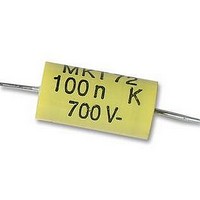
Capacitance
0.1UF
Voltage Rating, Dc
700V
Capacitor Dielectric Type
POLYPROPYLENE
Tolerance,
10%
Tolerance, -
10%
Temp, Op. Max
85(DEGREE C)
Temp, Op. Min
0(DEGREE


4
96
To produce a certain number of movements within a well defined time
period - in this case, the motor is used as a time base.
To produce a rotation movement requiring relatively low torque at
reasonable cost.
The Crouzet synchronous range consists of the following motor types :
➜ 1 Single direction
Either :
■
■
(We will see below how to ensure the correct direction of rotation).
In special applications it is possible to dispense with the anti-return totally
(SAR version). In this case, the motor may rotate in a clockwise direction.
➜ 2 Reversible
The motor rotates in either a clockwise or an anti-clockwise direction. The
direction of rotation is controlled by a capacitor.
This motor is characterised by a constant speed of rotation which is
independent of the load but linked to the supply frequency.
A synchronous motor maintains its speed of rotation until an overload
occurs.
When overload occurs, the motor loses synchronisation, ie. it stops and
develops an oscillation (vibration).
➜ Speed of rotation
This basic characteristic can be calculated as below :
Speed (in rpm) = 60 x f (en Hz)
f Hz : The frequency of the AC voltage through the coil.
P
Example :
A motor equipped with 5 pole pairs would give :
V = 60 x 50 = 600 rpm using a 50 Hz supply
and
V = 60 x 60 = 720 720 rpm using US supply (60 Hz)
Some principles of synchronous motors
Why choose a synchronous motor ?
How to select from the Crouzet range
Definition of a synchronous motor
Therefore the speed of rotation of a synchronous motor is defined
by its construction.
clockwise (CW or SA)
or anti-clockwise (ACL or SI)
: The number of pole pairs in the motor
(1 pair = 1 North Pole + 1 South Pole).
5
5
P
➜ Construction of a permanent magnet synchronous motor
Single direction
Technology
Our single direction motors are only available with a mechanical anti-
return. This assembly offers the double advantage of being a relatively
simple technical design while offering good performance.
The permanent magnet rotor has at its periphery a number of alternating
NORTH and SOUTH poles equal to the number of poles on the stator.
The latter, energised by a single coil connected to an AC supply,
produces a magnetic asymmetry which positions the rotor when stopped
in such a way that it is attracted by an oscillating torque when the current
is switched on.
This start-up condition would cause the motor to turn in either direction
if a mechanical device called an «anti-return» did not define and impose
the direction of rotation.
➜ Principle of operation
The principle assumes an electro-magnet : a permanent NS magnet
rotates around axis O in the air-gap of the electro-magnet, perpendicular
to the lines of magnetic force.
Let us suppose that this moving permanent magnet reaches the position
marked in figure 1. If the relative positions of the electro-magnet poles are
as shown in this figure, the magnet will be repelled and tend to oscillate
around an equilibrium position at 180° to direction S’ N ’ .
When the permanent magnet is just past this position (figure 2) and the
polarity of the electro-magnet is reversed, the magnet will be repelled and
return to its previous position, and so on.
Stator cover
Casing poles S.N.S.N.S.N
Cover poles N.S.N.S.N.S
Figure 1
Anti-return
Rotor
Stator casing
Induction coil
Figure 2
Related parts for 26231941
Image
Part Number
Description
Manufacturer
Datasheet
Request
R

Part Number:
Description:
SCREW SOCKET (OT08PC)
Manufacturer:
Crouzet USA
Datasheet:

Part Number:
Description:
PANEL PLATE FOR 813
Manufacturer:
Crouzet USA
Datasheet:
Part Number:
Description:
Controller; CTD46 Dual Display Temperature, 1/16 DIN, NEMA 4X, 110/220VAC
Manufacturer:
Crouzet USA
Datasheet:

Part Number:
Description:
11R1084
Manufacturer:
Crouzet USA
Datasheet:
Part Number:
Description:
11R1086
Manufacturer:
Crouzet USA
Datasheet:
Part Number:
Description:
11R1087
Manufacturer:
Crouzet USA
Datasheet:
Part Number:
Description:
11R1089
Manufacturer:
Crouzet USA
Datasheet:
Part Number:
Description:
11R1078
Manufacturer:
Crouzet USA
Datasheet:
Part Number:
Description:
11R1079
Manufacturer:
Crouzet USA
Datasheet: