26231941 Crouzet USA, 26231941 Datasheet - Page 72
26231941
Manufacturer Part Number
26231941
Description
CAPACITOR, MOTOR MEDIUM TORQUE CAPACITOR, MOTOR MEDIUM TORQUE
Manufacturer
Crouzet USA
Datasheet
1.26231909.pdf
(196 pages)
Specifications of 26231941
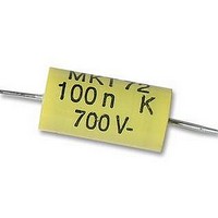
Capacitance
0.1UF
Voltage Rating, Dc
700V
Capacitor Dielectric Type
POLYPROPYLENE
Tolerance,
10%
Tolerance, -
10%
Temp, Op. Max
85(DEGREE C)
Temp, Op. Min
0(DEGREE


2
72
1.1. Composition of the driving part:
Brushless motors comprise 3 main elements:
- A fixed part, the stator, which has three groups of coils, called the
three phases of the motor. These coils operate as electromagnets and
generate various orientations of magnetic field regularly distributed
around the central shaft of the motor.
- A rotating part, the rotor, which has permanent magnets. Like the
needle of a compass, these magnets permanently drive the rotor to try
to align itself with the magnetic field of the stator. For optimum service
life of the motor, the rotor is mounted on ball bearings.
- Three "Hall effect" magnetic sensors. These sensors provide informa-
tion on the position of the rotor magnets at all times.
1.2. The integrated control electronics:
Crouzet brushless motors incorporate their control electronics as
standard. The control electronics control the phases of the motor,
regulate the speed and incorporate the encoder function.
Basic concepts
Brushless motors and geared motors
Principle
Inputs: On/off
Direction Speed
Torque (*)
Outputs:
Encoder
Direction info (*)
Torque info (*)
Electronic
plate
Hall effect
sensors
electronics
Control
Stator
(coils)
Control of
coils
Stator
Magnetic field
Rotor
N
S
Rotor
Field
Ball bearings
Hall effect
(magnets)
sensors
Rotor
Rotational
movement
- The control electronics determine the position of the rotor using the
Hall effect sensors. The electronics deduce from the sensors the orien-
tation to give to the magnetic field of the stator. During rotation, they
control the three coils to regularly adjust the orientation of the field to
the position of the rotor, in order to drive it in the direction chosen by
the user.
- By modulating the current in the coils, the electronics can accelerate
or slow down the motor and thus regulate its speed. They can also
orient the magnetic field in order to brake the movement of the rotor to
bring it to a standstill.
- By limiting the current in the coils, the electronics can also limit the
torque of the motor, and activate the corresponding output
- The electronics also generate the outputs of the built-in encoder using
the Hall effect sensors.
2.1. What is 4-quadrant regulation?
The four zones of a torque/speed diagram are known as ‘quadrants’:
- A positive speed represents clockwise rotation, and a negative speed
anti-clockwise
- A positive torque represents motor operation, and a negative torque
brake operation.
1-quadrant regulation operates in a single direction of rotation, with no
possibility of braking. In the event of overspeed, the regulator cuts off
the current until the motor is braked by the load
The principle is identical for 2-quadrant regulation, but in both direc-
tions of rotation. This operating mode is offered as an option on
Crouzet brushless motors, when required by a specific application.
4-quadrant regulation also operates in both directions of rotation, but
also allows braking. In the event of overspeed, the motor is involved in
the braking and the system quickly loses speed.
All Crouzet brushless motors have 4-quadrant regulation as
standard.
Speed regulation
Reverse operation
2
3
Motor
Brake
Speed axis
4
1
Clockwise
Related parts for 26231941
Image
Part Number
Description
Manufacturer
Datasheet
Request
R

Part Number:
Description:
SCREW SOCKET (OT08PC)
Manufacturer:
Crouzet USA
Datasheet:

Part Number:
Description:
PANEL PLATE FOR 813
Manufacturer:
Crouzet USA
Datasheet:
Part Number:
Description:
Controller; CTD46 Dual Display Temperature, 1/16 DIN, NEMA 4X, 110/220VAC
Manufacturer:
Crouzet USA
Datasheet:

Part Number:
Description:
11R1084
Manufacturer:
Crouzet USA
Datasheet:
Part Number:
Description:
11R1086
Manufacturer:
Crouzet USA
Datasheet:
Part Number:
Description:
11R1087
Manufacturer:
Crouzet USA
Datasheet:
Part Number:
Description:
11R1089
Manufacturer:
Crouzet USA
Datasheet:
Part Number:
Description:
11R1078
Manufacturer:
Crouzet USA
Datasheet:
Part Number:
Description:
11R1079
Manufacturer:
Crouzet USA
Datasheet: