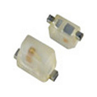
NCP18XH103K0SRB Murata, NCP18XH103K0SRB Datasheet - Page 16

NCP18XH103K0SRB
Manufacturer Part Number
NCP18XH103K0SRB
Description
Thermistors - NTC 10K OHM 10%
Manufacturer
Murata
Type
NTCr
Series
NCPr
Datasheet
1.NCP18XH103K0SRB.pdf
(59 pages)
Specifications of NCP18XH103K0SRB
Description Of Terminals
Leadless
Mounting Style
Surface Mount
Pin Count
2
Screening Level
Automotive
Resistance @ 25c
10kohm
Percentage Of Resistance Tolerance @ 25c
±10
Accuracy
±1
Operating Temperature Min Deg. C
-40C
Operating Temperature Max Deg. C
125C
Product Length (mm)
1.6mm
Product Height (mm)
0.8mm
Product Depth (mm)
0.8mm
Resistance
10 KOhms
Tolerance
10 %
Operating Temperature Range
- 40 C to + 125 C
Package / Case
0603
Current Rating
0.31 mAmp
Power Rating
100 mW
Lead Free Status / RoHS Status
Compliant
!Note
• This PDF catalog is downloaded from the website of Murata Manufacturing co., ltd. Therefore, it’s specifications are subject to change or our products in it may be discontinued without advance notice. Please check with our
• This PDF catalog has only typical specifications because there is no space for detailed specifications. Therefore, please approve our product specifications or transact the approval sheet for product specifications before ordering.
sales representatives or product engineers before ordering.
!Note
• The Test Condition specification (*1,*2) is applied to the follow P/N.
P/N: NCP15XH103**SR*, NCP15WL233**SR*, NCP15WL333**SR*, NCP15WL473**SR*, NCP15WL683**SR*, NCP15WL104**SR*,
(*1) Resistance(R
(*2) Resisitance(R
No. AEC-Q200 Test Item
10
11
12
13
1
2
3
4
5
6
7
8
9
NCP15WL154**SR*, NCP15WB473**SR*, NCP15WF104**SR*, NCP18XH103**SR*,
B-constant(B
B-constant(B
Pre-and Post-
Stress
Electrical Test
High Temperature
Exposure
(Storage)
Temperature
Cycling
Moisture
Resistance
Biased Humidity
Operational Life
External Visual
Physical
Dimension
Terminal Strengh
(Leaded)
Resistance to
Solvents
Mechanical Shock
Vibration
Resistance to
Soldering Heat
• Please read rating and !CAUTION (for storage, operating, rating, soldering, mounting and handling) in this catalog to prevent smoking and/or burning, etc.
• This catalog has only typical specifications because there is no space for detailed specifications. Therefore, please approve our product specifications or transact the approval sheet for product specifications before ordering.
25/50
25/50
25
25
) change should be less than 1%
) change should be less than 5%
) change should be less than 1%
) change should be less than 1%
(*1)
•Resistance(R
•B-constant(B
•No visible damage.
•Resistance(R
•B-constant(B
•No visible damage.
•Resistance(R
•B-constant(B
•No visible damage.
(*2)
•Resistance(R
•B-constant(B
•No visible damage.
•Resistance(R
•B-constant(B
•No visible damage.
No defects of abnormalities.
Within the specified dimensions.
•Resistance(R
•B-constant(B2
•No visible damage.
•Resistance(R
•B-constant(B
•No visible damage.
(*1)
•Resistance(R
•B-constant(B
•No visible damage.
(*1)
•Resistance(R
•B-constant(B
•No visible damage.
For NTC Thermistors Chip Type Specifications and Test Methods
25/50
25/50
25/50
25/50
25/50
25/50
25/50
25/50
25
25
25
25
25
25
25
25
25
5/50
) change should be less than ±5%.
) change should be less than ±5%.
) change should be less than ±5%.
) change should be less than ±10%.
) change should be less than ±5%.
) change should be less than ±5%.
) change should be less than ±5%.
) change should be less than ±5%.
) change should be less than ±5%.
) change should be less than ±2%.
) change should be less than ±2%.
) change should be less than ±2%.
) change should be less than ±2%.
) change should be less than ±2%.
) change should be less than ±2%.
) change should be less than ±2%.
) change should be less than ±2%.
) change should be less than ±2%.
Specifications
N/A
-
125±3 °C in air for 1000 hours.
Measurement at 24±2 hours after test condition.
Perform the 1000 cycles according to the four heat treatments
listed in the following table.
Measurement at 24±2 hours after test condition.
Apply the 24 hours heat (25 to 65 °C) and humidity (80 to 98%)
treatment shown below, 10 consecutive times.
Measurement at 24±2 hours after test condition.
85±2 °C, 85%RH in air for 1000 hours
with Permissive Operating Current.
Measurement at 24±2 hours after test condition.
125±3 °C in air for 1000 hours
with Permissive Operating Current.
Measurement at 24±2 hours after test condition.
Visual Inspection.
Using calipers
Per MIL-STD-202 Method 215
Solvent 1: 1 part (by volume) of isopropyl alcohol
Per MIL-STD-202 Method 213 Test Condition F
1500g's, 0.5ms, In 3 directions perpendicularly intersecting
each other (total 18 times).
Simple harmonic motion between 10Hz to 2.0k Hz and back to
10 Hz of max. amplitude 1.5mm for 20 minutes. This motion
should be applied for 12 times in each of 3 mutually
perpendicular directions (total of 36 times).
Per MIL-STD-202 Method 210
Test Condition B, 260 °C for 10 +/-1 seconds
Temp. (deg.C)
Time (min.)
Step
70
65
60
55
50
45
40
35
30
25
20
15
10
5
0
0 1 2 3 4 5 6 7 8 9 10 11 12 13 14 15 16 17 18 19 20 21 22 23 24
3 part (by volume) of mineral spirits.
Initial measurement
-55+0/-3
Humidity
90 to 98%
AEC-Q200 Test Methods
15±3
1
+10
-2
deg.C
One cycle 24 hours
Humidity
80 to 98%
Room Temp.
Continued on the following page.
2
1
Humidity
90 to 98%
125+3/-0
15±3
Humidity
80 to 98%
3
Humidity
90 to 98%
Room Temp.
Hours
4
1
R03E.pdf
15
07.3.21
2


