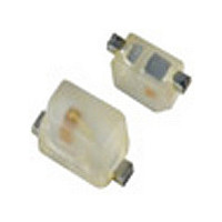
NCP18XH103K0SRB Murata, NCP18XH103K0SRB Datasheet - Page 35

NCP18XH103K0SRB
Manufacturer Part Number
NCP18XH103K0SRB
Description
Thermistors - NTC 10K OHM 10%
Manufacturer
Murata
Type
NTCr
Series
NCPr
Datasheet
1.NCP18XH103K0SRB.pdf
(59 pages)
Specifications of NCP18XH103K0SRB
Description Of Terminals
Leadless
Mounting Style
Surface Mount
Pin Count
2
Screening Level
Automotive
Resistance @ 25c
10kohm
Percentage Of Resistance Tolerance @ 25c
±10
Accuracy
±1
Operating Temperature Min Deg. C
-40C
Operating Temperature Max Deg. C
125C
Product Length (mm)
1.6mm
Product Height (mm)
0.8mm
Product Depth (mm)
0.8mm
Resistance
10 KOhms
Tolerance
10 %
Operating Temperature Range
- 40 C to + 125 C
Package / Case
0603
Current Rating
0.31 mAmp
Power Rating
100 mW
Lead Free Status / RoHS Status
Compliant
5
!Note
• This PDF catalog is downloaded from the website of Murata Manufacturing co., ltd. Therefore, it’s specifications are subject to change or our products in it may be discontinued without advance notice. Please check with our
• This PDF catalog has only typical specifications because there is no space for detailed specifications. Therefore, please approve our product specifications or transact the approval sheet for product specifications before ordering.
sales representatives or product engineers before ordering.
!Note
1. Solder and Flux
2. Cleaning Conditions and Drying
3. Soldering Conditions
34
For POSISTORr Chip Type !Caution/Notice
To remove the flux after soldering, observe the following
(2) Drying
In your mounting process, observe the following points in
order to avoid deterioration of the characteristics or
Notice (Soldering and Mounting) 0603 (1608) Size
(1) Solder Paste
(2) Flux
points in order to avoid deterioration of the characteristics
or any change to the external electrodes quality.
(1) Cleaning Conditions
destruction of this product. The mounting quality of this
product may also be affected by the mounting conditions,
shown in the points below.
(1) Printing Conditions of Solder Paste
A sufficient cleaning should be applied to remove flux completely.
(a) Flow Soldering: Use Sn:Pb=60:40wt%,
(b) Reflow Soldering: Use Sn:Pb=60:40wt%,
Use rosin-based flux. Do not use strong acidic flux (with
halide content exceeding 0.2wt%).
2-propanol
After cleaning, promptly dry this product.
(a) Recommended thickness of solder paste printing
(b) After soldering, the solder fillet should be a height
(c) Too much solder gives too strong mechanical stress
• Please read rating and !CAUTION (for storage, operating, rating, soldering, mounting and handling) in this catalog to prevent smoking and/or burning, etc.
• This catalog has only typical specifications because there is no space for detailed specifications. Therefore, please approve our product specifications or transact the approval sheet for product specifications before ordering.
Sn:Pb=63:37wt%, Sn:Ag:Cu=96.5:3.0:0.5wt% or
equivalent type of solder.
Sn:Pb=63:37wt%, Sn:Ag:Cu=96.5:3.0:0.5wt% or
equivalent type of solder paste.
For your reference, we are using '63Sn/37Pb
RMA9086 90-3-M18', manufactured by Alpha Metals
Japan Ltd., '96.5Sn/3.0Ag/0.5Cu M705-221BM5-42-
11', manufactured by Senju Metal Industry Co., Ltd.
for any Internal tests of this product.
should be from 0.15 to 0.20mm.
from 0.2 mm to the thickness of this product (see the
figure at right).
to this product. Such stress may cause cracking or
other mechanical damage. Also, it can destroy the
electrical performance of this product.
Solvent
Less than 5 minutes
Less than 2 minutes
Dipping Cleaning
at room temp.
at 40˚C max.
or
Ultrasonic Cleaning
Less than 1 minute
20W/L Frequency
of several 10kHz
to 100kHz.
E
Electrode
Solder
Continued on the following page.
T
Solder
0.2mm V T V E
R03E.pdf
07.3.21


