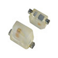
NCP18XH103K0SRB Murata, NCP18XH103K0SRB Datasheet - Page 32

NCP18XH103K0SRB
Manufacturer Part Number
NCP18XH103K0SRB
Description
Thermistors - NTC 10K OHM 10%
Manufacturer
Murata
Type
NTCr
Series
NCPr
Datasheet
1.NCP18XH103K0SRB.pdf
(59 pages)
Specifications of NCP18XH103K0SRB
Description Of Terminals
Leadless
Mounting Style
Surface Mount
Pin Count
2
Screening Level
Automotive
Resistance @ 25c
10kohm
Percentage Of Resistance Tolerance @ 25c
±10
Accuracy
±1
Operating Temperature Min Deg. C
-40C
Operating Temperature Max Deg. C
125C
Product Length (mm)
1.6mm
Product Height (mm)
0.8mm
Product Depth (mm)
0.8mm
Resistance
10 KOhms
Tolerance
10 %
Operating Temperature Range
- 40 C to + 125 C
Package / Case
0603
Current Rating
0.31 mAmp
Power Rating
100 mW
Lead Free Status / RoHS Status
Compliant
!Note
• This PDF catalog is downloaded from the website of Murata Manufacturing co., ltd. Therefore, it’s specifications are subject to change or our products in it may be discontinued without advance notice. Please check with our
• This PDF catalog has only typical specifications because there is no space for detailed specifications. Therefore, please approve our product specifications or transact the approval sheet for product specifications before ordering.
sales representatives or product engineers before ordering.
!Note
No.
11
12
13
10
1
2
3
4
5
6
7
8
9
Chip Type of POSISTORr for Overheat Protection Specifications and Test Methods
Operating Temp. 1
Operating Temp. 2
Resistance Value
(at 25˚C)
Withstanding
Voltage
Adhesive Strength
Vibration
Resistance
Resistance to
Bending of
Substance
Solderability
Soldering Heat
Resistance
Dry Heat
Resistance
Cold Resistance
Damp Heat
Resistance
Thermal Shock
• Please read rating and !CAUTION (for storage, operating, rating, soldering, mounting and handling) in this catalog to prevent smoking and/or burning, etc.
• This catalog has only typical specifications because there is no space for detailed specifications. Therefore, please approve our product specifications or transact the approval sheet for product specifications before ordering.
Item
3
-40 to +105°C
-40 to +125°C
The resistance value shall be within the specified tolerance.
Without damage
There is no detachment sign of electrode.
Normal appearance
Resistance change: not to exceed ±20%
Normal appearance
Resistance change: not to exceed ±20%
Min. 95% electrode is covered with new solder.
Resistance change: not to exceed ±20%
Normal appearance
Resistance change: not to exceed ±20%
Normal appearance
Resistance change: not to exceed ±20%
Rating Value
2
2
2
2
2
The temperature range with maximum voltage applied to the
POSISTORr.
The temperature range which with zero voltage applied to
POSISTORr after it was soldered to PCB.
After applying maximum operating voltage for 3 minutes and
leaving for 2 hours at 25°C, measured by applying voltage of
less than 1.5Vdc (by a direct current of less than 10mA).
We apply 120% of the maximum voltage to PTC by rising
gradually for 180±5 seconds at 25°C. (A protective resistor is to
be connected in series, and the inrush current through PTC
must be limited below maximum rated value.)
EIAJ ET-7403 term 9
Prepare soldered PTC to PCB 1 and add a force of 5.0N in the
direction shown below. (PTC=POSISTORr)
Soldered PTC to PCB 1
Vibrate for 4 hours in each of 3 mutually perpendicular planes for
a total of 12 hours. This test condition is according to "MIL-STD-
204D"
Soldered PTC on Test Board 1, and apply force on back side
of Test Board shown below:
JIS C 5102 term 8.4
Solder: Sn 63%/Pb 37% (or 60%/40%) solder paste
Soldered PTC to PCB
Soldered PTC to PCB
Soldered PTC to PCB
Soldered PTC to PCB
Flux: Containing less than 0.2wt% of chlorine.
Preheating: 150±5°C 3 minutes
Peak Temp.: 260±5°C 10±5 seconds (reflow)
PCB: JIS C 6484
Vibration: 10-2000-10Hz (20 min.)
Max. Amplitude: 3.0mm
Bending Speed: 1.0mm/s
Bending Strength: 2.0mm
Hold Time: 5±1 seconds
Board Dimension: 100A40A1.6t mm
Board Material: Glass Epoxy
Solder Temp.: 230±5°C
Solder: Sn63%/Pb37% (or 60%/40%)
Soaking Time: 3±0.5 seconds
Soaking Position: Until a whole electrode is soaked
+125±3°C leave for 1000±12 hours.
-40±3°C leave for 1000±12 hours.
+85±3°C 80-85%RH leave for 1000±12 hours.
Cycles: 1000 cycles
Step
1
2
Glass Epoxy PCB
Temp. (°C)
+125+3, -0
-55+0, -3
R230
45 2
Method of Examination
PTC
PTC
1
1
1
1
F
20
50
Time (minutes)
Continued on the following page.
45 2
30
30
Force
Glass Epoxy PCB
F
Bending
(in mm)
R03E.pdf
31
07.3.21
5


