XR21V1412IL-0B-EB Exar Corporation, XR21V1412IL-0B-EB Datasheet - Page 10
XR21V1412IL-0B-EB
Manufacturer Part Number
XR21V1412IL-0B-EB
Description
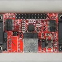
Interface Modules & Development Tools For XR21V1412 QFN32 USB, RS232;No Cables
Manufacturer
Exar Corporation
Series
-r
Specifications of XR21V1412IL-0B-EB
Interface Type
RS-232, USB
Operating Supply Voltage
3.3 V
Product
Interface Modules
Silicon Core Number
XR21V1412
Application Sub Type
UART
Kit Contents
Board
Main Purpose
Interface, USB 2.0 to UART
Embedded
No
Utilized Ic / Part
XR21V1412IL
Primary Attributes
-
Secondary Attributes
-
Silicon Manufacturer
Exar
Kit Application Type
Communication & Networking
For Use With/related Products
XR21V1412
Lead Free Status / Rohs Status
Lead free / RoHS Compliant


XR21V1412
2-CH FULL-SPEED USB UART
Error flags are also available from the ERROR_STATUS register and the interrupt packet, however these flags
are historical flags indicating that an error has occurred since the previous read of the status register.
Therefore, no conclusion can be drawn as to which specific byte(s) may have contained an actual error in this
manner.
Each UART has 6 GPIOs. By default, the GPIOs are general purpose I/Os. However, there are few modes
that can be enabled to add additional feature such as Auto RTS/CTS Flow control, Auto DTR/DSR Flow
Control or Transceiver Enable Control. See
GPIO5 and GPIO4 of the UART channel can be enabled as the RTS# and CTS# signals for Auto RTS/CTS
flow control when GPIO_MODE[2:0] = ’001’ and FLOW_CONTROL[2:0] = ’001’. Automatic RTS flow control is
used to prevent data overrun errors in local RX FIFO by de-asserting the RTS signal to the remote UART.
When there is room in the RX FIFO, the RTS pin will be re-asserted. Automatic CTS flow control is used to
prevent data overrun to the remote RX FIFO. The CTS# input is monitored to suspend/restart the local
transmitter (see
1.5.3
1.5.4
GPIO
Automatic RTS/CTS Hardware Flow Control
2nd byte
2nd byte
1st byte
1st byte
Figure
4):
7 6 5 4 3 2 1 0
7 6 5 4 3 2 1 0
x x x x O F B P
x x x x O F B 8
7 or 8 bit m ode
9 bit m ode
F
IGURE
Table
3. R
ECEIVE
14.
10
D
B = B reak
F = Fram ing E rror
B = B reak
F = Fram ing E rror
O = O verrun E rror
P = P arity E rror (= ‘0’ if not enabled)
x = ‘0’
O = O verrun E rror
ATA
x = ‘0’
7 = ‘0’ in 7 bit m ode
F
ORMAT
REV. 1.1.0
Related parts for XR21V1412IL-0B-EB
Image
Part Number
Description
Manufacturer
Datasheet
Request
R

Part Number:
Description:
2-ch Full-speed Usb Uart
Manufacturer:
Exar Corporation
Datasheet:
Part Number:
Description:
BiCMOS Fixed, Quad, Voltage Output, Single or Dual Supply 8-Bit Digital-to-Analog Converter
Manufacturer:
Exar Corporation
Datasheet:
Part Number:
Description:
Manufacturer:
Exar Corporation
Datasheet:
Part Number:
Description:
Voltage-Controlled Oscillator
Manufacturer:
Exar Corporation
Datasheet:
Part Number:
Description:
INTEGRATED LINE TRANSMITTER
Manufacturer:
Exar Corporation
Datasheet:
Part Number:
Description:
Monolithic Function Generator
Manufacturer:
Exar Corporation
Datasheet:
Part Number:
Description:
CMOS Microprocessor Compatible Double-Buffered 12-Bit Digital-to-Analog Converter
Manufacturer:
Exar Corporation
Datasheet:
Part Number:
Description:
CMOS 6 BIT HIGH SPEED ANALOG TO DIGITAL CONVERTER
Manufacturer:
Exar Corporation
Datasheet:
Part Number:
Description:
Manufacturer:
Exar Corporation
Datasheet:
Part Number:
Description:
Manufacturer:
Exar Corporation
Datasheet:
Part Number:
Description:
8-Channel, Voltage Output 10 MHz Input Bandwidth 8-Bit Multiplying DACs with Serial Digital Data Por
Manufacturer:
Exar Corporation
Datasheet:
Part Number:
Description:
15 V CMOS Multiplying10-Bit Digital-to-Analog Converter
Manufacturer:
Exar Corporation
Datasheet:
Part Number:
Description:
Monolithic Function Generator
Manufacturer:
Exar Corporation
Datasheet: