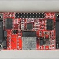
XR21V1412IL-0B-EB Exar Corporation, XR21V1412IL-0B-EB Datasheet - Page 11

XR21V1412IL-0B-EB
Manufacturer Part Number
XR21V1412IL-0B-EB
Description
Interface Modules & Development Tools For XR21V1412 QFN32 USB, RS232;No Cables
Manufacturer
Exar Corporation
Series
-r
Specifications of XR21V1412IL-0B-EB
Interface Type
RS-232, USB
Operating Supply Voltage
3.3 V
Product
Interface Modules
Silicon Core Number
XR21V1412
Application Sub Type
UART
Kit Contents
Board
Main Purpose
Interface, USB 2.0 to UART
Embedded
No
Utilized Ic / Part
XR21V1412IL
Primary Attributes
-
Secondary Attributes
-
Silicon Manufacturer
Exar
Kit Application Type
Communication & Networking
For Use With/related Products
XR21V1412
Lead Free Status / Rohs Status
Lead free / RoHS Compliant
REV. 1.1.0
Auto DTR/DSR hardware flow control behaves the same as the Auto RTS/CTS hardware flow control
described above except that it uses the DTR# and DSR# signals.
FLOW_CONTROL[2:0] = ’001’.
GPIO_MODE[2:0] = ’010’.
When software flow control is enabled, the V1412 compares the receive data characters with the programmed
Xon or Xoff characters. If the received character matches the programmed Xoff character, the V1412 will halt
transmission as soon as the current character has completed transmission. Data transmission is resumed
when a received character matches the Xon character.
FLOW_CONTROL[2:0] = ’010’.
The V1412 device has two address matching modes which are also set by the flow control register using
modes 3 and 4. These modes are intended for a multi-drop network application. In these modes, the
XON_CHAR register holds a unicast address and the XOFF_CHAR holds a multicast address. A unicast
address is used by a transmitting master to broadcast an address to all attached slave devices that is intended
for only one slave device. A multicast address is used to broadcast an address intended for more than one
recipient device. Each attached slave device should have a unique unicast address value stored in the
XON_CHAR register, while multiple slaves may have the same multicast adderss stored in the XOFF_CHAR
register. An address match occurs when an address byte (9th bit or parity bit is ’1’) is received that matches the
value stored in either the XON_CHAR or XOFF_CHAR register.
F
1.5.5
1.5.6
1.5.7
IGURE
4. A
Automatic DTR/DSR Hardware Flow Control
Automatic XON/XOFF Software Flow Control
Multidrop Mode with address matching
UTO
(RXA FIFO
CTSB#
RXA FIFO
Interrupt)
RTSA#
TXB
INTA
RTS
Trigger Reached
Receiver FIFO
Trigger Level
Local UART
Transmitter
Auto CTS
Auto RTS
UARTA
Monitor
AND
Data Starts
Receive
CTS F
Data
Assert RTS# to Begin
1
2
Transmission
Trigger Level
LOW
3
4
RX FIFO
GPIO3 and GPIO2 become DTR# and DSR#, respectively, when
RTSA#
TXA
CTSA#
RXA
C
ON
ONTROL
ON
5
O
PERATION
7
Threshold
RTS High
11
6
8
OFF
Suspend
OFF
RTSB#
CTSB#
Software flow control is enabled when
RTS Low
Threshold
RXB
TXB
Restart
9
10
11
For Auto hardware flow control,
2-CH FULL-SPEED USB UART
Trigger Reached
Remote UART
ON
Trigger Level
Receiver FIFO
12
Auto CTS
Auto RTS
Transmitter
UARTB
Monitor
ON
Trigger Level
RX FIFO
RTSCTS1
XR21V1412


