IDP09E60 Infineon Technologies, IDP09E60 Datasheet
IDP09E60
Specifications of IDP09E60
Available stocks


Related parts for IDP09E60

IDP09E60 Summary of contents
Page 1
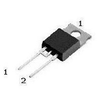
... Symbol FSM I FRM Page 1 Product Summary V RRM jmax P-TO220-3.SMD P-TO220-2-2. Marking Pin 1 PIN 2 C D09E60 D09E60 NC Value 600 RRM 19 29.5 tot 57.7 32.7 -55...+175 T stg 255 IDP09E60 IDB09E60 600 1.5 V 175 °C PIN Unit °C °C 2003-07-31 ...
Page 2
... Device on 40mm*40mm*1.5mm epoxy PCB FR4 with 6cm² (one layer, 70 µm thick) copper area for drain connection. PCB is vertical without blown air. Rev.2 Symbol R thJC R thJA R thJA = 25 °C, unless otherwise specified j Symbol Page 2 IDP09E60 IDB09E60 Values Unit min. typ. max 2.6 K ...
Page 3
... Symbol t rr =25°C j =125°C j =150° rrm =25°C j =125°C j =150° =25°C j =125°C j =150° =25°C j =125°C j =150°C j Page 3 IDP09E60 IDB09E60 Values Unit min. typ. max 110 - - 112 - 343 - - 585 - - ...
Page 4
... Rev.2 2 Diode forward current I = f(T F parameter 125 °C 175 Typ. diode forward voltage 1.6 1.4 1.2 1 Page ≤ 175° 100 125 ) j 2 18A 9A 4,5A 1 -60 - IDP09E60 IDB09E60 °C 175 T C 100 °C 160 T j 2003-07-31 ...
Page 5
... V 700 800 A/µs 1000 di /dt F Page 5 /dt 400V 125 ° 18A 9A 4.5A 200 300 400 500 600 700 /dt 400V 125° 200 300 400 500 600 700 IDP09E60 IDB09E60 800 A/µs 1000 di /dt F 18A 9A 4.5A 800 A/µs 1000 di /dt F 2003-07-31 ...
Page 6
... Max. transient thermal impedance thJC p parameter : IDP09E60 10 K single pulse - Rev 0.50 0.20 0.10 0.05 0.02 0. Page 6 IDP09E60 IDB09E60 2003-07-31 ...
Page 7
... Rev symbol Page 7 IDP09E60 IDB09E60 TO-220-2-2 dimensions [mm] [inch] min max min max A 9.70 10.10 0.3819 0.3976 B 15.30 15.90 0.6024 0.6260 C 0.65 0.85 0.0256 0.0335 D 3.55 3.85 0.1398 0.1516 E 2.60 3.00 0.1024 0.1181 F 9.00 9.40 0.3543 0.3701 G 13.00 14.00 0.5118 0.5512 H 17.20 17 ...
Page 8
... R S 1.70 2.50 T 0.50 0.65 10.8 typ. U 1.35 typ. V 6.43 typ. W 4.60 typ. X 9.40 typ. Y 16.15 typ. Z Page 8 IDP09E60 IDB09E60 [inch] min max 0.3858 0.3937 0.0512 typ. 0.0492 0.0689 0.0374 0.0453 0.1 typ. 0.0283 0.0335 0.2 typ. 0.1693 0.1772 0.0504 0.0551 ...
Page 9
... Life support devices or systems are intended to be implanted in the human body support and/or maintain and sustain and/or protect human life. If they fail reasonable to assume that the health of the user or other persons may be endangered. Rev.2 Page 9 IDP09E60 IDB09E60 2003-07-31 ...