XPSAC3421P SQUARE D, XPSAC3421P Datasheet - Page 237
XPSAC3421P
Manufacturer Part Number
XPSAC3421P
Description
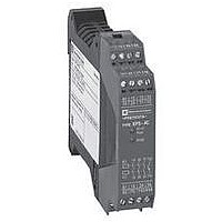
SAFETY RELAY 300V 2.5A PREVENTA
Manufacturer
SQUARE D
Datasheet
1.XPSMCCPC.pdf
(274 pages)
Specifications of XPSAC3421P
Contact Current Max
60mA
Contact Voltage Ac Nom
115V
Contact Configuration
3NO
Relay Mounting
DIN Rail
External Height
66mm
External Width
114mm
External Depth
22.5mm
Rohs Compliant
Yes


10
1
2
3
4
5
6
7
8
9
Wiring diagrams
ESC: External start conditions.
Input: S11, S12, S13 or S21, S22, S23.
Unused inputs must be jumpered: i.e.: if only input S11, S12, S13 is used, then terminals S21 and S23 must be jumpered.
The order in which the inputs are wired or jumpered will not affect operation.
Principle:
page 2/234
+
2/236
XPSDMB
Wiring to category 4 conforming to EN 954-1/ISO 13849-1. Example with 2-pole N.C. + N.O. (N.C. staggered) contact.
For example with 3-pole N.C. + N.C. + N.O. contact see page 3/58
Wiring to category 3 conforming to EN 954-1/ISO 13849-1. Example with 3 switches with 2-pole N.C. + N.O. (N.C. staggered) contacts.
0 V
24 V
A1
A2
S11
S21
F1
XPS DMB
S1.1
S1.2
S1.3
S12
S22
XCS DM
XCS DM
XCS DM
Characteristics:
page 2/234
S13
S23
S11
S21
Guard 2 closed
Supply A1/A2
Fault
K1/K2
Guard 1 closed
S1
S2
S12
S22
XCS DM
XCS DM
Logic
S13
S23
Safety automation system solutions
Preventa™ safety relay modules types
XPSDMB, XPSDME
For non-contact safety interlock (coded magnetic)
switch monitoring
References:
page 2/235
Fault
Start
S3
Y34
Y1
ESC
2 solid-state outputs
Wiring Diagrams:
page 2/236
K1/K2
K3
K4
Y44
Y2
To PLC
K1
K2
K3
Dimensions:
page 2/260
Channel 1
13
14
Safety outputs
K4
Channel 2
23
24
1
Related parts for XPSAC3421P
Image
Part Number
Description
Manufacturer
Datasheet
Request
R


Part Number:
Description:
Pushbutton, Non-Illum'd Red "STOP", Momentary, 1NO-1NC, Square 30mm, 10A, 600V
Manufacturer:
SQUARE D
Datasheet:

Part Number:
Description:
KITS,TWIDO? PROGRAMMABLE CONTROLLERS,KITS,TWIDOPACK STARTER KIT - ADVANCED LEVEL,PROGRAMMABLE CONTROLLERS,TWIDO? PROGRAMMABLE CONTROLLERS ,SQUARE D
Manufacturer:
SQUARE D

Part Number:
Description:
LAMPS,INDICATOR,STACKABLE,LAMPS, STACKABLE INDICATOR,VISUAL INDICATING SIGNALS,XVB SERIES INDICATING BANKS ,SQUARE D
Manufacturer:
SQUARE D
Part Number:
Description:
LAMPS,INDICATOR,STACKABLE,LAMPS, STACKABLE INDICATOR,VISUAL INDICATING SIGNALS,XVB SERIES INDICATING BANKS ,SQUARE D
Manufacturer:
SQUARE D
Datasheet:
Part Number:
Description:
I/O EXTENDER MODULE 4 D IN & 2 D OUTPUT
Manufacturer:
SQUARE D
Datasheet:
Part Number:
Description:
CB ACCESSORY, UNDERVOLTAGE TRIP 48V DC
Manufacturer:
SQUARE D
Datasheet: