1N5818G ON Semiconductor, 1N5818G Datasheet - Page 3
1N5818G
Manufacturer Part Number
1N5818G
Description
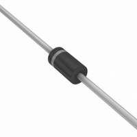
DIODE SCHOTTKY 1A 30V DO-41
Manufacturer
ON Semiconductor
Datasheet
1.1N5819RLG.pdf
(7 pages)
Specifications of 1N5818G
Voltage - Forward (vf) (max) @ If
550mV @ 1A
Voltage - Dc Reverse (vr) (max)
30V
Current - Average Rectified (io)
1A
Current - Reverse Leakage @ Vr
1mA @ 30V
Diode Type
Schottky
Speed
Fast Recovery =< 500ns, > 200mA (Io)
Mounting Type
Through Hole
Package / Case
DO-204AL, DO-41, Axial
Product
Schottky Diodes
Peak Reverse Voltage
30 V
Forward Continuous Current
1 A @ Ta=55C
Max Surge Current
25 A
Configuration
Single
Forward Voltage Drop
0.875 V @ 3 A
Maximum Reverse Leakage Current
1000 uA
Operating Temperature Range
- 65 C to + 125 C
Mounting Style
Through Hole
Lead Free Status / RoHS Status
Lead free / RoHS Compliant
Reverse Recovery Time (trr)
-
Capacitance @ Vr, F
-
Lead Free Status / Rohs Status
Lead free / RoHS Compliant
Other names
1N5818G
1N5818GOS
1N5818GOS
Available stocks
Company
Part Number
Manufacturer
Quantity
Price
Company:

Part Number:
1N5818G
Manufacturer:
ON Semiconductor
Quantity:
220
Part Number:
1N5818G
Manufacturer:
ON/安森美
Quantity:
20 000


runaway must be considered when operating this rectifier at
reverse voltages above 0.1 V
accomplished by use of equation (1).
taking reverse power dissipation and thermal runaway into
consideration. The figures solve for a reference temperature
as determined by equation (2).
ambient temperature at which thermal runaway occurs or
where T
transition from one boundary condition to the other is
evident on the curves of Figures 1, 2, and 3 as a difference
in the rate of change of the slope in the vicinity of 115°C. The
data of Figures 1, 2, and 3 is based upon dc conditions. For
use in common rectifier circuits, Table 1 indicates suggested
factors for an equivalent dc voltage to use for conservative
design, that is:
various rectifier circuits and the reverse characteristics of
Schottky diodes.
12−volt dc supply using a bridge circuit with capacitive filter
such that I
Voltage = 10 V
**Values given are for the 1N5818. Power is slightly lower for the
1N5817 because of its lower forward voltage, and higher for the
1N5819.
Substituting equation (2) into equation (1) yields:
**Note that V
where T
Square Wave
Reverse power dissipation and the possibility of thermal
Figures 1, 2, and 3 permit easier use of equation (1) by
Inspection of equations (2) and (3) reveals that T
The factor F is derived by considering the properties of the
EXAMPLE: Find T
Sine Wave
Step 1. Find V
Step 1. Find
Step 2. Find T
Step 1. Find
Step 3. Find P
Step 4. Find T
Step 4. Find
NOTE 3. — DETERMINING MAXIMUM RATINGS
Circuit
Load
T
T
P
P
A(max)
A(max)
J(max)
J
R(AV)
R
F(AV)
DC
= 125°C, when forward power is zero. The
qJA
@
R(PK)
= 0.4 A (I
=
=
=
=
=
=
∴ V
@ V
T
(rms)
I
I
(FM)
A(max)
A(max)
R
R(equiv)
F(AV)
(AV)
T
Maximum allowable ambient temperature
Maximum allowable junction temperature
(125°C or the temperature at which thermal
runaway occurs, whichever is lowest)
Average forward power dissipation
Average reverse power dissipation
Junction−to−ambient thermal resistance
≈ 2.0 V
V
J(max)
from Figure 2. Read T
T
R(equiv)
R
A(max)
R(equiv)
Resistive
, R
T
= 9.2 V and R
from Figure 4. **Read P
= 10 and IF(AV) = 0.5 A.
R
= 109 − (80) (0.5) = 69°C.
from equation (3).
0.75
. Read F = 0.65 from Table 1,
qJA
0.5
F(AV)
= T
− R
A(max)
in(PK)
= T
= (1.41)(10)(0.65) = 9.2 V.
J(max)
= V
= 80°C/W.
qJA
Half Wave
R
= 0.5 A), I
.
RWM
in(PK)
P
− R
F(AV)
for 1N5818 operated in a
− R
qJA
qJA
. Proper derating may be
x F
qJA
Capacitive*
− R
P
= 80°C/W.
F(AV)
P
R
(FM)
qJA
R(AV)
1.3
1.5
†Use line to center tap voltage for V
= 109°C
P
/I
F(AV)
R(AV)
(AV)
1N5817, 1N5818, 1N5819
Table 1. Values for Factor F
= 0.5 W
= 10, Input
R
http://onsemi.com
Resistive
is the
0.75
0.5
(1)
(2)
(3)
(4)
Full Wave, Bridge
3
°
°
°
125
115
105
125
115
105
125
115
105
95
85
75
95
85
75
95
85
75
4.0
2.0
3.0
R
in
Figure 1. Maximum Reference Temperature
Capacitive
qJA
.
5.0
Figure 2. Maximum Reference Temperature
Figure 3. Maximum Reference Temperature
0.65
0.75
4.0
(°C/W) = 110
R
qJA
3.0
(°C/W) = 110
5.0
60
80
7.0
R
V
V
V
qJA
R
R
R
4.0
, DC REVERSE VOLTAGE (VOLTS)
, DC REVERSE VOLTAGE (VOLTS)
, DC REVERSE VOLTAGE (VOLTS)
(°C/W) = 110
7.0
5.0
10
80
1N5817
Resistive
Full Wave, Center Tapped* †
60
1N5818
1N5819
1.0
1.5
10
7.0
80
60
15
10
15
20
40
30
40
40
Capacitive
23
30
20
1.3
1.5
15
30
30
23
23
20
30
40
Related parts for 1N5818G
Image
Part Number
Description
Manufacturer
Datasheet
Request
R

Part Number:
Description:
ON Semiconductor [VOLTAGE REGULATOR]
Manufacturer:
ON Semiconductor
Datasheet:
Part Number:
Description:
357-036-542-201 CARDEDGE 36POS DL .156 BLK LOPRO
Manufacturer:
ON Semiconductor
Datasheet:
Part Number:
Description:
357-036-542-201 CARDEDGE 36POS DL .156 BLK LOPRO
Manufacturer:
ON Semiconductor
Datasheet:
Part Number:
Description:
357-036-542-201 CARDEDGE 36POS DL .156 BLK LOPRO
Manufacturer:
ON Semiconductor
Datasheet:
Part Number:
Description:
357-036-542-201 CARDEDGE 36POS DL .156 BLK LOPRO
Manufacturer:
ON Semiconductor
Datasheet:
Part Number:
Description:
357-036-542-201 CARDEDGE 36POS DL .156 BLK LOPRO
Manufacturer:
ON Semiconductor
Datasheet:
Part Number:
Description:
357-036-542-201 CARDEDGE 36POS DL .156 BLK LOPRO
Manufacturer:
ON Semiconductor
Datasheet:
Part Number:
Description:
357-036-542-201 CARDEDGE 36POS DL .156 BLK LOPRO
Manufacturer:
ON Semiconductor
Datasheet:
Part Number:
Description:
357-036-542-201 CARDEDGE 36POS DL .156 BLK LOPRO
Manufacturer:
ON Semiconductor
Datasheet:
Part Number:
Description:
357-036-542-201 CARDEDGE 36POS DL .156 BLK LOPRO
Manufacturer:
ON Semiconductor
Datasheet:
Part Number:
Description:
357-036-542-201 CARDEDGE 36POS DL .156 BLK LOPRO
Manufacturer:
ON Semiconductor
Datasheet:
Part Number:
Description:
Manufacturer:
ON Semiconductor
Datasheet:
Part Number:
Description:
Manufacturer:
ON Semiconductor
Datasheet:
Part Number:
Description:
Manufacturer:
ON Semiconductor
Datasheet: