1N5818G ON Semiconductor, 1N5818G Datasheet - Page 6
1N5818G
Manufacturer Part Number
1N5818G
Description
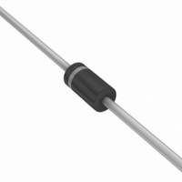
DIODE SCHOTTKY 1A 30V DO-41
Manufacturer
ON Semiconductor
Datasheet
1.1N5819RLG.pdf
(7 pages)
Specifications of 1N5818G
Voltage - Forward (vf) (max) @ If
550mV @ 1A
Voltage - Dc Reverse (vr) (max)
30V
Current - Average Rectified (io)
1A
Current - Reverse Leakage @ Vr
1mA @ 30V
Diode Type
Schottky
Speed
Fast Recovery =< 500ns, > 200mA (Io)
Mounting Type
Through Hole
Package / Case
DO-204AL, DO-41, Axial
Product
Schottky Diodes
Peak Reverse Voltage
30 V
Forward Continuous Current
1 A @ Ta=55C
Max Surge Current
25 A
Configuration
Single
Forward Voltage Drop
0.875 V @ 3 A
Maximum Reverse Leakage Current
1000 uA
Operating Temperature Range
- 65 C to + 125 C
Mounting Style
Through Hole
Lead Free Status / RoHS Status
Lead free / RoHS Compliant
Reverse Recovery Time (trr)
-
Capacitance @ Vr, F
-
Lead Free Status / Rohs Status
Lead free / RoHS Compliant
Other names
1N5818G
1N5818GOS
1N5818GOS
Available stocks
Company
Part Number
Manufacturer
Quantity
Price
Company:

Part Number:
1N5818G
Manufacturer:
ON Semiconductor
Quantity:
220
Part Number:
1N5818G
Manufacturer:
ON/安森美
Quantity:
20 000


†For information on tape and reel specifications, including part orientation and tape sizes, please refer to our Tape and Reel Packaging
*This package is inherently Pb−Free.
ORDERING INFORMATION
majority carrier conduction, it is not subject to junction
diode forward and reverse recovery transients due to
minority carrier injection and stored charge. Satisfactory
circuit analysis work may be performed by using a model
consisting of an ideal diode in parallel with a variable
capacitance. (See Figure 10.)
operation will be satisfactory up to several megahertz. For
example, relative waveform rectification efficiency is
approximately 70 percent at 2.0 MHz, e.g., the ratio of dc
power to RMS power in the load is 0.28 at this frequency,
whereas perfect rectification would yield 0.406 for sine
wave inputs. However, in contrast to ordinary junction
diodes, the loss in waveform efficiency is not indicative of
power loss: it is simply a result of reverse current flow
through the diode capacitance, which lowers the dc output
voltage.
Specifications Brochure, BRD8011/D.
1N5817
1N5817G
1N5817RL
1N5817RLG
1N5818
1N5818G
1N5818RL
1N5818RLG
1N5819
1N5819G
1N5819RL
1N5819RLG
Since current flow in a Schottky rectifier is the result of
Rectification efficiency measurements show that
NOTE 6. — HIGH FREQUENCY OPERATION
Device
1N5817, 1N5818, 1N5819
http://onsemi.com
Axial Lead*
Axial Lead*
Axial Lead*
Axial Lead*
Axial Lead*
Axial Lead*
Axial Lead*
Axial Lead*
Axial Lead*
Axial Lead*
Axial Lead*
Axial Lead*
Package
6
200
100
70
50
30
20
10
0.4
0.6
0.8
Figure 10. Typical Capacitance
1.0
T
f = 1.0 MHz
J
V
R
1N5817
= 25°C
, REVERSE VOLTAGE (VOLTS)
1N5818
2.0
1N5819
5000 / Tape & Reel
5000 / Tape & Reel
5000 / Tape & Reel
5000 / Tape & Reel
5000 / Tape & Reel
5000 / Tape & Reel
4.0
1000 Units / Bag
1000 Units / Bag
1000 Units / Bag
1000 Units / Bag
1000 Units / Bag
1000 Units / Bag
Shipping
6.0
8.0
10
†
20
40
Related parts for 1N5818G
Image
Part Number
Description
Manufacturer
Datasheet
Request
R

Part Number:
Description:
ON Semiconductor [VOLTAGE REGULATOR]
Manufacturer:
ON Semiconductor
Datasheet:
Part Number:
Description:
357-036-542-201 CARDEDGE 36POS DL .156 BLK LOPRO
Manufacturer:
ON Semiconductor
Datasheet:
Part Number:
Description:
357-036-542-201 CARDEDGE 36POS DL .156 BLK LOPRO
Manufacturer:
ON Semiconductor
Datasheet:
Part Number:
Description:
357-036-542-201 CARDEDGE 36POS DL .156 BLK LOPRO
Manufacturer:
ON Semiconductor
Datasheet:
Part Number:
Description:
357-036-542-201 CARDEDGE 36POS DL .156 BLK LOPRO
Manufacturer:
ON Semiconductor
Datasheet:
Part Number:
Description:
357-036-542-201 CARDEDGE 36POS DL .156 BLK LOPRO
Manufacturer:
ON Semiconductor
Datasheet:
Part Number:
Description:
357-036-542-201 CARDEDGE 36POS DL .156 BLK LOPRO
Manufacturer:
ON Semiconductor
Datasheet:
Part Number:
Description:
357-036-542-201 CARDEDGE 36POS DL .156 BLK LOPRO
Manufacturer:
ON Semiconductor
Datasheet:
Part Number:
Description:
357-036-542-201 CARDEDGE 36POS DL .156 BLK LOPRO
Manufacturer:
ON Semiconductor
Datasheet:
Part Number:
Description:
357-036-542-201 CARDEDGE 36POS DL .156 BLK LOPRO
Manufacturer:
ON Semiconductor
Datasheet:
Part Number:
Description:
357-036-542-201 CARDEDGE 36POS DL .156 BLK LOPRO
Manufacturer:
ON Semiconductor
Datasheet:
Part Number:
Description:
Manufacturer:
ON Semiconductor
Datasheet:
Part Number:
Description:
Manufacturer:
ON Semiconductor
Datasheet:
Part Number:
Description:
Manufacturer:
ON Semiconductor
Datasheet: