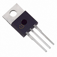
SGP30N60 Infineon Technologies, SGP30N60 Datasheet

SGP30N60
Specifications of SGP30N60
Available stocks
Related parts for SGP30N60
SGP30N60 Summary of contents
Page 1
... Allowed number of short circuits: <1000; time between short circuits: >1s. PG-TO-220-3-1 http://www.infineon.com/igbt Marking CE(sat) j 2.5V G30N60 PG-TO-220-3-1 150°C 2.5V G30N60 150°C Symbol jmax SGP30N60 SGW30N60 PG-TO-247-3 Package PG-TO-247-3 Value Unit 600 112 112 ±20 V 165 mJ µs 10 250 W -55...+150 °C 260 Rev. 2.5 Nov. 09 ...
Page 2
... 20V 30A 25V 0V 80V 30A PG-TO-220-3-1 E PG-TO-247-3-21 I ≤10µ 5V ≤ 600V ≤ 150° SGP30N60 SGW30N60 Max. Value Unit 0.5 K Value Unit min. Typ. max. 600 - - V 1.7 2.1 2.4 - 2.5 3 µ 3000 - - 100 1600 1920 pF - 150 180 - 92 110 - 140 182 ...
Page 3
... 00V 30A 11Ω σ σ Energy losses include E “tail” and diode reverse recovery due to dynamic test circuit in Figure E. σ 3 SGP30N60 SGW30N60 Value Unit min. typ. max 291 349 - 0.64 0. 0.65 0.85 - 1.29 1.62 Value Unit min. typ. max ...
Page 4
... Limited by bond wire 40A 30A 20A 10A 0A 125°C 25°C 50° CASE TEMPERATURE C Figure 4. Collector current as a function of case temperature ≤ 15V, T ≤ 150° SGP30N60 SGW30N60 t =4 µ µ µ s 200 µ s 1ms DC 100V 1000V - EMITTER VOLTAGE ≤ 150°C) j 75° ...
Page 5
... Figure 6. Typical output characteristics (T = 150°C) j 4.0V 3.5V 3.0V 2.5V 2.0V 1.5V 1.0V 8V 10V -50°C 0° JUNCTION TEMPERATURE j Figure 8. Typical collector-emitter saturation voltage as a function of junction temperature (V = 15V SGP30N60 SGW30N60 EMITTER VOLTAGE I = 60A 30A C 50°C 100°C 150°C Rev. 2.5 Nov. 09 ...
Page 6
... GE C Dynamic test circuit in Figure E) 5.5V 5.0V 4.5V 4.0V 3.5V 3.0V 2.5V 2.0V 150°C -50° JUNCTION TEMPERATURE j Figure 12. Gate-emitter threshold voltage as a function of junction temperature (I = 0.7mA SGP30N60 SGW30N60 t d(off d(on Ω 30 Ω 40 Ω , GATE RESISTOR = 150° 400V 30A, max. ...
Page 7
... E * 0. K/W 0. K/W off single pulse -4 10 K/W 1µs 10µs 150° Figure 16. IGBT transient thermal impedance as a function of pulse width ( SGP30N60 SGW30N60 include losses off Ω 30 Ω 40 Ω , GATE RESISTOR = 150° 400V 30A, τ 0.3681 0.0555 -3 0.0938 1.26* ...
Page 8
... V , GATE GE Figure 20. Typical short circuit collector current as a function of gate-emitter voltage ≤ 600V 150° SGP30N60 SGW30N60 C iss C oss C rss 20V 30V - EMITTER VOLTAGE 14V 16V 18V 20V - EMITTER VOLTAGE Rev. 2.5 Nov. 09 ...
Page 9
... PG-TO-220-3-1 9 SGP30N60 SGW30N60 Rev. 2.5 Nov. 09 ...
Page 10
... SGP30N60 SGW30N60 10 Rev. 2.5 Nov. 09 ...
Page 11
... Figure A. Definition of switching times Figure B. Definition of switching losses SGP30N60 SGW30N60 τ τ ( Figure D. Thermal equivalent circuit Figure E. Dynamic test circuit Leakage inductance L and Stray capacity C 11 τ =180nH σ =900pF. σ Rev. 2.5 Nov. 09 ...
Page 12
... Life support devices or systems are intended to be implanted in the human body or to support and/or maintain and sustain and/or protect human life. If they fail reasonable to assume that the health of the user or other persons may be endangered. SGP30N60 SGW30N60 12 Rev. 2.5 ...


