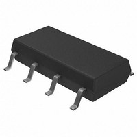
S-35399A03-J8T2G Seiko Instruments, S-35399A03-J8T2G Datasheet - Page 12

S-35399A03-J8T2G
Manufacturer Part Number
S-35399A03-J8T2G
Description
Real Time Clock 2-wire Real Time Clock
Manufacturer
Seiko Instruments
Datasheet
1.S-35399A03-J8T2G.pdf
(53 pages)
Specifications of S-35399A03-J8T2G
Supply Voltage (max)
3 V
Supply Voltage (min)
1.3 V
Maximum Operating Temperature
+ 85 C
Minimum Operating Temperature
- 40 C
Mounting Style
SMD/SMT
Rtc Bus Interface
Serial
Supply Current
0.34 uA
Package / Case
SOP-8
Lead Free Status / RoHS Status
Lead free / RoHS Compliant
12
2-WIRE REAL-TIME CLOCK
S-35399A03
2. Status register 1
B0 : POC
B1 : BLD
B2, B3 : INT2, INT1
B4, B5 : SC1, SC0
B6 :
B7 : RESET
Status register 1 is a 1-byte register that is used to display and set various modes. The bit configuration is shown below.
This flag is used to confirm whether the power is on. The power-on detection circuit operates at power-on and B0 is
set to “1”. This flag is Read-only. Once it is read, it is automatically set to “0”. When this flag is “1”, be sure to initialize.
Regarding the operation after power-on, refer to “ Power-on Detection Circuit and Register Status” .
This flag is set to “1” when the power supply voltage decreases to the level of detection voltage (V
can detect a drop in the power supply voltage. This flag is set to “1” once, is not set to “0” again even if the power
supply increases to the level of detection voltage (V
to initialize. Regarding the operation of the power supply voltage detection circuit, refer to “
Voltage Detection Circuit” .
This flag indicates the time set by alarm and when the time has reached it. This flag is set to “1” when the time that
users set by using the alarm interrupt function has come. The INT1 flag in “1” at alarm 1 interrupt mode, the INT2 flag
in “1” at alarm 2 interrupt mode. Set “0” in INT1AE (B5 in the status register 2) or in INT2AE (B1 in the status register
2) after reading “1” in the INT1 flag or in the INT2 flag. This flag is Read-only. This flag is read once, is set to “0”
automatically.
These flags configure a 2-bit SRAM type register that can be freely set by users.
This flag is used to set 12-hour or 24-hour expression.
The internal IC is initialized by setting this bit to “1”. This bit is Write-only. It is always “0” when Read. When applying
the power supply voltage to the IC, be sure to write “1” to this bit to initialize the circuit. Regarding each status of data
after initialization, refer to “ Register Status After Initialization ”.
0 : 12-hour expression
1 : 24-hour expression
12
/
RESET
24
B7
W
12 / 24
R/W
B6
R/W
SC0
B5
Figure 10 Status Register 1
Seiko Instruments Inc.
R/W
SC1
B4
DET
) or more. This flag is Read-only. When this flag is “1”, be sure
INT1
B3
R
R:
W:
R/W:
INT2
B2
R
Read
Write
Read/Write
BLD
B1
R
POC
B0
R
Low Power Supply
DET
Rev.2.0
) or less. Users
_00


