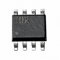
IRF7324D1PBF International Rectifier, IRF7324D1PBF Datasheet

IRF7324D1PBF
Specifications of IRF7324D1PBF
Related parts for IRF7324D1PBF
IRF7324D1PBF Summary of contents
Page 1
... D A Peak Diode Recovery dV/dt Linear Derating Factor T Operating Junction and J T Storage Temperature Range STG Thermal Resistance Parameter Junction-to-Drain Lead R θJL Junction-to-Ambient R θJA Notes through … are on page 8 www.irf.com IRF7324D1PbF FETKY Top View @ 10V GS @ 10V Typ. g ––– ...
Page 2
... IRF7324D1PbF MOSFET Electrical Characteristics @ T Parameter BV Drain-to-Source Breakdown Voltage DSS R Static Drain-to-Source On-Resistance DS(on) V Gate Threshold Voltage GS(th) I Drain-to-Source Leakage Current DSS I Gate-to-Source Forward Leakage GSS Gate-to-Source Reverse Leakage gfs Forward Transconductance Q Total Gate Charge g Q Gate-to-Source Charge gs Q Gate-to-Drain Charge gd t Turn-On Delay Time ...
Page 3
... Power Mosfet Characteristics 100 10 1 0.1 10 0.1 100 25° 150°C 10.0 1.0 0.1 5.0 6.0 7.0 0.4 IRF7324D1PbF VGS TOP -7.5V -5.0V -4.0V -3.5V -3.0V -2.5V -2.0V BOTTOM -1.5V ≤ 60µs PULSE WIDTH -1. 150° Drain-to-Source Voltage ( 150° 25° ...
Page 4
... IRF7324D1PbF 1 -2. -4.5V 1.0 0.5 -60 -40 - Junction Temperature (°C) 0.4 0.3 0.2 0.1 0.0 2.0 4.0 6 Gate-to-Source Voltage (V) Fig 7. Typical On-Resistance Vs. Gate Voltage 4 Power Mosfet Characteristics 0.164 0.160 0.156 0.152 0.148 0.144 0.140 80 100 120 140 160 0.0 Fig 6. Typical On-Resistance Vs. ...
Page 5
... SINGLE PULSE (THERMAL RESPONSE) 0.1 0.0001 0.001 Fig 11. Maximum Effective Transient Thermal Impedance, Junction-to-Ambient www.irf.com Power Mosfet Characteristics -2. 100 0.01 0 Rectangular Pulse Duration (sec) 1 IRF7324D1PbF -16V VDS= -10V Total Gate Charge (nC Notes: 1. Duty factor Peak thJA ...
Page 6
... IRF7324D1PbF Schottky Diode Characteristics 10 1 0.1 0.0 0.2 0.4 0.6 Forward Voltage Drop - V Forward Votage Drop - V Fig. 12 -Typical Forward Voltage Drop Characteristics 150° 125°C Fig Typical Values of Reverse 25°C J 0.8 1.0 (V) ( Fig.14 - Typical Junction capacitance T = 50°C J 25°C 00° ...
Page 7
... A S UBS T RAT E. SO-8 (Fetky) Part Marking Information EXAMPLE: THIS IS AN IRF7807D1 (FETKY) INTERNATIONAL www.irf.com 0.10 [.004 6.46 [.255] 3X 1.27 [.050] XXXX 807D1 RECTIFIER LOGO IRF7324D1PbF INCHES MILLIMET ERS DIM MIN MAX MIN MAX A .0532 .0688 1.35 1.75 A1 .0040 .0098 0.10 0.25 b ...
Page 8
... IRF7324D1PbF SO-8 (Fetky) Tape and Reel TERMINAL NUMBER 1 8.1 ( .318 ) 7.9 ( .312 ) NOTES: 1. CONTROLLING DIMENSION : MILLIMETER. 2. ALL DIMENSIONS ARE SHOWN IN MILLIMETERS(INCHES). 3. OUTLINE CONFORMS TO EIA-481 & EIA-541. 330.00 (12.992) MAX. NOTES : 1. CONTROLLING DIMENSION : MILLIMETER. 2. OUTLINE CONFORMS TO EIA-481 & EIA-541. Notes: Repetitive rating; pulse width limited by maximum junction temperature (see figure 11) ‚ ...


