BFR 720L3RH E6327 Infineon Technologies, BFR 720L3RH E6327 Datasheet

TRANS RF NPN 4V 20MA TSLP-3

BFR 720L3RH E6327

Manufacturer Part Number
BFR 720L3RH E6327
Description
TRANS RF NPN 4V 20MA TSLP-3
Manufacturer
Infineon Technologies
Datasheet

Specifications of BFR 720L3RH E6327

Package / Case
TSFP-3
Transistor Type
NPN
Voltage - Collector Emitter Breakdown (max)
4.7V
Frequency - Transition
45GHz
Noise Figure (db Typ @ F)
0.5dB ~ 0.8dB @ 1.8GHz ~ 6Ghz
Gain
24dB
Power - Max
80mW
Dc Current Gain (hfe) (min) @ Ic, Vce
160 @ 13mA, 3V
Current - Collector (ic) (max)
20mA
Mounting Type
Surface Mount
Dc Collector/base Gain Hfe Min
160
Minimum Operating Temperature
- 65 C
Mounting Style
SMD/SMT
Transistor Polarity
NPN
Maximum Operating Frequency
45 GHz
Collector- Emitter Voltage Vceo Max
4 V
Emitter- Base Voltage Vebo
1.2 V
Continuous Collector Current
20 mA
Power Dissipation
80 mW
Maximum Operating Temperature
+ 150 C
Lead Free Status / RoHS Status
Lead free / RoHS Compliant
Other names
BFR720L3RHE6327XT
NPN Silicon Germanium RF Transistor
Target data sheet
• High gain ultra low noise RF transistor
• Provides outstanding performance for
• Optimum gain and noise figure
• Ideal for WLAN applications
• Outstanding noise figure F = 0.5 dB at 1.8 GHz
• High maximum stable and available gain
• 150 GHz f
• Extremly small and flat leadless package
• Pb-free (RoHS compliant) package
• Qualified according AEC Q101
ESD (Electrostatic discharge) sensitive device, observe handling precaution!
Type
BFR720L3RH
for low current operation
a wide range of wireless applications
up to 10 GHz and more
at low current operation
Outstanding noise figure F = 0.8 dB at 6 GHz
G
height 0.32 mm max.
ms
= 24 dB at 1.8 GHz, G
T
-Silicon Germanium technology
ma
Marking
R3
= 16.5 dB at 6 GHz
1 = B
1
Pin Configuration
2 = C
3 = E
1
BFR720L3RH
Package
TSLP-3-9
2
2008-07-04
3

Related parts for BFR 720L3RH E6327

BFR 720L3RH E6327 Summary of contents

Page 1

NPN Silicon Germanium RF Transistor Target data sheet • High gain ultra low noise RF transistor for low current operation • Provides outstanding performance for a wide range of wireless applications GHz and more • Optimum gain ...

Page 2

Maximum Ratings Parameter Collector-emitter voltage T > 0 °C A ≤ 0 ° Collector-emitter voltage Collector-base voltage Emitter-base voltage Collector current Base current 1) Total power dissipation T ≤ tbd S Operating junction temperature range Storage junction temperature ...

Page 3

Electrical Characteristics at T Parameter AC Characteristics (verified by random sampling) Transition frequency mA GHz C CE Collector-base capacitance MHz ...

Page 4

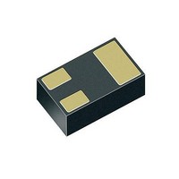
Package Outline Pin 1 marking 1) Dimension applies to plated terminal Foot Print For board assembly information please refer to Infineon website "Packages" 0.6 0.225 0.15 Copper Marking Layout (Example) Standard Packing Reel ø180 mm = 15.000 ...

Page 5

... For information on the types in question please contact your nearest Infineon Technologies Office. Infineon Technologies Components may only be used in life-support devices or systems with the express written approval of Infineon Technologies failure of such components can reasonably be expected to cause the failure of that life-support device or system affect the safety or effectiveness of that device or system ...

Related keywords