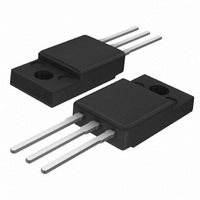
BT151X-650R,127 NXP Semiconductors, BT151X-650R,127 Datasheet - Page 6

BT151X-650R,127
Manufacturer Part Number
BT151X-650R,127
Description
THYRISTOR 650V 12A SOT186A
Manufacturer
NXP Semiconductors
Datasheet
1.BT151X-500R127.pdf
(11 pages)
Specifications of BT151X-650R,127
Package / Case
TO-220-3 Full Pack
Scr Type
Standard Recovery
Voltage - Off State
650V
Voltage - Gate Trigger (vgt) (max)
1.5V
Voltage - On State (vtm) (max)
1.75V
Current - On State (it (av)) (max)
7.5A
Current - On State (it (rms)) (max)
12A
Current - Gate Trigger (igt) (max)
15mA
Current - Hold (ih) (max)
20mA
Current - Off State (max)
500µA
Current - Non Rep. Surge 50, 60hz (itsm)
120A, 132A
Operating Temperature
-40°C ~ 125°C
Mounting Type
Through Hole
Current - On State (it (rms) (max)
12A
Rated Repetitive Off-state Voltage Vdrm
650 V
Breakover Current Ibo Max
110 A
On-state Rms Current (it Rms)
12 A
Off-state Leakage Current @ Vdrm Idrm
0.1 mA
Gate Trigger Voltage (vgt)
0.4 V
Gate Trigger Current (igt)
2 mA
Holding Current (ih Max)
20 mA
Forward Voltage Drop
1.4 V
Mounting Style
Through Hole
Maximum Operating Temperature
+ 125 C
Minimum Operating Temperature
- 40 C
Off-state Capacitance Co
10 pF
Repetitive Peak Forward Blocking Voltage
650 V
Lead Free Status / RoHS Status
Lead free / RoHS Compliant
Other names
934038060127
BT151X-650R
BT151X-650R
BT151X-650R
BT151X-650R
Philips Semiconductors
7. Characteristics
Table 6:
T
9397 750 13162
Product data sheet
Symbol
Static characteristics
I
I
I
V
V
I
Dynamic characteristics
dV
t
t
GT
L
H
D
gt
q
j
Fig 7. Normalized gate trigger voltage as a function of
T
GT
= 25 C unless otherwise stated
, I
V
D
GT
V
R
/dt
GT
(25 C)
1.6
1.2
0.8
0.4
(T
j
junction temperature.
)
50
Characteristics
Parameter
gate trigger current
latching current
holding current
on-state voltage
gate trigger voltage
off-state leakage
current
critical rate of rise of
off-state voltage
gate controlled
turn-on time
circuit commuted
turn-on time
0
50
Conditions
V
V
V
I
V
V
T
V
T
V
exponential waveform;
I
I
V
I
dI
dV
T
TM
G
TM
j
j
D
D
D
D
D
D
DM
D
100
TM
gate open circuit
R
= 23 A;
= 125 C
= 125 C
= 0.1 A; dI
D
= 12 V; I
= 12 V; I
= 12 V; I
= 12 V; I
= V
= V
= 67% V
= 40 A; V
= 20 A; V
GK
/dt = 50 V/ s; R
/dt = 30 A/ s;
= 67% V
001aaa953
T
j
DRM(max)
DRM(max)
= 100
( C)
Figure 9
150
T
GT
GT
T
DRM(max)
G
D
R
Rev. 04 — 9 June 2004
= 0.1 A;
= 0.1 A;
DRM(max)
/dt = 5 A/ s
= 0.1 A;
= 0.1 A;
= V
= 25 V;
; I
; V
T
R
DRM(max)
= 0.1 A;
= V
GK
; T
; T
Figure 8
Figure 7
j
= 100
RRM(max)
Figure 12
Figure 10
Figure 11
= 125 C;
j
= 125 C;
Fig 8. Normalized gate trigger current as a function of
I
;
GT
I
GT
(25 C)
(T
;
j
)
3
2
1
0
junction temperature.
50
Min
-
-
-
-
-
0.25
-
50
200
-
-
0
© Koninklijke Philips Electronics N.V. 2004. All rights reserved.
BT151X series
Typ
2
10
7
1.4
0.6
0.4
0.1
130
1000
2
70
50
100
Max
15
40
20
1.75
1.5
-
0.5
-
-
-
-
001aaa952
T
j
( C)
150
Thyristors
Unit
mA
mA
mA
V
V
V
mA
V/ s
V/ s
s
s
6 of 11


