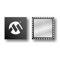
PIC16F1519-E/MV Microchip Technology, PIC16F1519-E/MV Datasheet - Page 59

PIC16F1519-E/MV
Manufacturer Part Number
PIC16F1519-E/MV
Description
40-pin, 28KB Flash, 1024B RAM, 10-bit ADC, 2xCCP, SPI, MI2C, EUSART, 2.3V-5.5V 4
Manufacturer
Microchip Technology
Series
PIC® XLP™ 16Fr
Datasheet
1.PIC16F1516-EMV.pdf
(344 pages)
Specifications of PIC16F1519-E/MV
Processor Series
PIC16F151x
Core
PIC
Data Bus Width
8 bit
Program Memory Type
Flash
Program Memory Size
16 KB
Data Ram Size
1 KB
Interface Type
I2C, SPI, USART
Maximum Clock Frequency
20 MHz
Number Of Programmable I/os
36
Number Of Timers
3
Operating Supply Voltage
2.3 V to 5.5 V
Maximum Operating Temperature
+ 125 C
Mounting Style
SMD/SMT
Package / Case
QFN-40
Core Processor
PIC
Core Size
8-Bit
Speed
20MHz
Connectivity
I²C, LIN, SPI, UART/USART
Peripherals
Brown-out Detect/Reset, POR, PWM, WDT
Number Of I /o
36
Eeprom Size
-
Ram Size
1K x 8
Voltage - Supply (vcc/vdd)
2.3 V ~ 5.5 V
Data Converters
A/D 28x10b
Oscillator Type
Internal
Operating Temperature
-40°C ~ 125°C
Lead Free Status / Rohs Status
Details
- Current page: 59 of 344
- Download datasheet (3Mb)
5.3
The system clock source can be switched between
external and internal clock sources via software using
the System Clock Select (SCS) bits of the OSCCON
register. The following clock sources can be selected
using the SCS bits:
• Default system oscillator determined by FOSC
• Secondary oscillator 32 kHz crystal
• Internal Oscillator Block (INTOSC)
5.3.1
The System Clock Select (SCS) bits of the OSCCON
register selects the system clock source that is used for
the CPU and peripherals.
• When the SCS bits of the OSCCON register = 00,
• When the SCS bits of the OSCCON register = 01,
• When the SCS bits of the OSCCON register = 1x,
When switching between clock sources, a delay is
required to allow the new clock to stabilize. These oscil-
lator delays are shown in
5.3.2
The Oscillator Start-up Time-out Status (OSTS) bit of
the OSCSTAT register indicates whether the system
clock is running from the external clock source, as
defined by the FOSC<2:0> bits in the Configuration
Word 1, or from the internal clock source. In particular,
OSTS indicates that the Oscillator Start-up Timer
(OST) has timed out for LP, XT or HS modes. The OST
does not reflect the status of the secondary oscillator.
2011 Microchip Technology Inc.
bits in Configuration Word 1
the system clock source is determined by value of
the FOSC<2:0> bits in the Configuration Word 1.
the system clock source is the secondary
oscillator.
the system clock source is chosen by the internal
oscillator frequency selected by the IRCF<3:0>
bits of the OSCCON register. After a Reset, the
SCS bits of the OSCCON register are always
cleared.
Note:
Clock Switching
SYSTEM CLOCK SELECT (SCS)
BITS
Any automatic clock switch, which may
occur
Fail-Safe Clock Monitor, does not update
the SCS bits of the OSCCON register. The
user can monitor the OSTS bit of the
OSCSTAT register to determine the current
system clock source.
OSCILLATOR START-UP TIME-OUT
STATUS (OSTS) BIT
from
Table
Two-Speed
5-1.
Start-up
Preliminary
or
5.3.3
The secondary oscillator is a separate crystal oscillator
associated with the Timer1 peripheral. It is optimized
for timekeeping operations with a 32.768 kHz crystal
connected between the SOSCO and SOSCI device
pins.
The secondary oscillator is enabled using the
T1OSCEN control bit in the T1CON register. See
Section 18.0 “Timer1 Module with Gate Control”
more information about the Timer1 peripheral.
5.3.4
The user must ensure that the secondary oscillator is
ready to be used before it is selected as a system clock
source. The Secondary Oscillator Ready (SOSCR) bit
of the OSCSTAT register indicates whether the
secondary oscillator is ready to be used. After the
SOSCR bit is set, the SCS bits can be configured to
select the secondary oscillator.
PIC16(L)F1516/7/8/9
SECONDARY OSCILLATOR
SECONDARY OSCILLATOR READY
(SOSCR) BIT
DS41452B-page 59
for
Related parts for PIC16F1519-E/MV
Image
Part Number
Description
Manufacturer
Datasheet
Request
R

Part Number:
Description:
IC, 8BIT MCU, PIC16F, 32MHZ, SOIC-18
Manufacturer:
Microchip Technology
Datasheet:

Part Number:
Description:
IC, 8BIT MCU, PIC16F, 32MHZ, SSOP-20
Manufacturer:
Microchip Technology
Datasheet:

Part Number:
Description:
IC, 8BIT MCU, PIC16F, 32MHZ, DIP-18
Manufacturer:
Microchip Technology
Datasheet:

Part Number:
Description:
IC, 8BIT MCU, PIC16F, 32MHZ, QFN-28
Manufacturer:
Microchip Technology
Datasheet:

Part Number:
Description:
IC, 8BIT MCU, PIC16F, 32MHZ, QFN-28
Manufacturer:
Microchip Technology
Datasheet:

Part Number:
Description:
IC, 8BIT MCU, PIC16F, 32MHZ, QFN-28
Manufacturer:
Microchip Technology
Datasheet:

Part Number:
Description:
IC, 8BIT MCU, PIC16F, 32MHZ, SSOP-20
Manufacturer:
Microchip Technology
Datasheet:

Part Number:
Description:
IC, 8BIT MCU, PIC16F, 20MHZ, DIP-40
Manufacturer:
Microchip Technology
Datasheet:

Part Number:
Description:
IC, 8BIT MCU, PIC16F, 32MHZ, QFN-28
Manufacturer:
Microchip Technology
Datasheet:

Part Number:
Description:
IC, 8BIT MCU, PIC16F, 20MHZ, MQFP-44
Manufacturer:
Microchip Technology
Datasheet:

Part Number:
Description:
IC, 8BIT MCU, PIC16F, 20MHZ, QFN-20
Manufacturer:
Microchip Technology
Datasheet:

Part Number:
Description:
IC, 8BIT MCU, PIC16F, 32MHZ, QFN-28
Manufacturer:
Microchip Technology
Datasheet:

Part Number:
Description:
MCU 14KB FLASH 768B RAM 64-TQFP
Manufacturer:
Microchip Technology
Datasheet:

Part Number:
Description:
7 KB Flash, 384 Bytes RAM, 32 MHz Int. Osc, 16 I/0, Enhanced Mid Range Core, Low
Manufacturer:
Microchip Technology

Part Number:
Description:
14KB Flash, 512B RAM, 256B EEPROM, LCD, 1.8-5.5V 40 UQFN 5x5x0.5mm TUBE
Manufacturer:
Microchip Technology
Datasheet:


