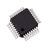
MC33910G5AC Freescale, MC33910G5AC Datasheet - Page 67

MC33910G5AC
Manufacturer Part Number
MC33910G5AC
Description
Manufacturer
Freescale
Datasheet
1.MC33910G5AC.pdf
(90 pages)
Specifications of MC33910G5AC
Turn Off Delay Time
10us
Number Of Drivers
2
Operating Temperature (min)
-40C
Operating Temperature (max)
125C
Operating Temperature Classification
Automotive
Lead Free Status / RoHS Status
Compliant
Available stocks
Company
Part Number
Manufacturer
Quantity
Price
Company:
Part Number:
MC33910G5AC
Manufacturer:
Freescale Semiconductor
Quantity:
10 000
Part Number:
MC33910G5AC
Manufacturer:
FREESCALE
Quantity:
20 000
Company:
Part Number:
MC33910G5ACR2
Manufacturer:
Freescale Semiconductor
Quantity:
10 000
INTERRUPT (IRQ)
faults to the MCU while in Normal and Normal Request mode
or to signal a wake-up from Stop mode. This active low output
will transition to high, only after the interrupt is acknowledged
by a SPI read of the respective status bits.
WATCHDOG CONFIGURATION (WDCONF)
watchdog. A resistor can be connected to this pin to configure
the window watchdog period. When connected directly to
ground, the watchdog will be disabled. When this pin is left
open, the watchdog period is fixed to its lower precision
internal default value (150 ms typical).
GROUND CONNECTION (AGND, PGND, LGND)
Power ground pins.
regulator.
return as in the LIN interface pin.
together.
DIGITAL/ANALOG (L1)
digital input, which can be sampled by reading the SPI and
used for wake-up when 33910 is in Low Power mode or used
as analog inputs for the analog multiplexer. When used to
sense voltage outside the module, a 33kohm series resistor
must be used on each input.
operate in Cyclic-Sense mode. In this mode, one of the high
side switches is configured to be periodically turned on and
sample the wake-up input. If a state change is detected
between two cycles a wake-up is initiated. The 33910 can
also wake-up from Stop or Sleep by a simple state change on
L1.
pins is scaled down by an selectable internal voltage divider
and can be routed to the ADOUT0 output through the analog
multiplexer.
be disabled as digital input and remains disabled in low
Power mode. No wake-up feature is available in that
condition.
multiplexer, the voltage divider is disconnected from that
input.
67
33910
FUNCTIONAL DESCRIPTION
FUNCTIONAL PIN DESCRIPTION
The IRQ pin is a digital output used to signal events or
The WDCONF pin is the configuration pin for the internal
The AGND, PGND and LGND pins are the Analog and
The AGND pin is the ground reference of the voltage
The PGND and LGND pins are used for high current load
Note: PGND, AGND and LGND pins must be connected
The L1 pin is a multi purpose input. It can be used as a
When used as a wake-up input L1 can be configured to
When used as analog input, the voltage present on the L1
Note: If L1 input is selected in the analog multiplexer, it will
When the L1 input is not selected in the analog
HIGH SIDE OUTPUTS (HS1 AND HS2)
relays or lamps. Their structure is connected to the VS2
supply pin. The pins are short-circuit protected and also
protected against overheating.
signal applied to the PWMIN input pin.
Power mode for the cyclic-sense of the wake input.
POWER SUPPLY (VS1 AND VS2)
application, VS1 and VS2 pins must be protected against
reverse battery connection and negative transient voltages,
with external components. These pins sustain standard
automotive voltage conditions such as load dump at 40 V.
VS2 pin, all other internal blocks are supplied by VS1 pin.
VOLTAGE SENSE PIN (VSENSE)
is protected against battery reverse connection. The voltage
present in this input is scaled down by an internal voltage
divider, and can be routed to the ADOUT0 output pin and
used by the MCU to read the battery voltage.
+40 V, and down to -27 V, allowing this pin to be connected
directly to the battery line. It is strongly recommended to
connect a 10kohm resistor in series with this pin for protection
purposes.
HALL SENSOR SWITCHABLE SUPPLY PIN (HVDD)
sensors. While in Normal mode, this current limited output
can be controlled through the SPI.
capacitor to stabilize the regulated output voltage.
+5V MAIN REGULATOR OUTPUT (VDD)
stabilize the regulated output voltage. The VDD pin is
intended to supply a microcontroller. The pin is current limited
against shorts to GND and over-temperature protected.
with its full drive capabilities and the output current is limited.
down.
These high side switches are able to drive loads such as
HS1and HS2 are controlled by SPI and can respond to a
The HS1 and HS2 outputs can also be used during Low
Those are the battery level voltage supply pins. In an
The high side switches (HS1 and HS2) are supplied by the
This input can be connected directly to the battery line. It
The ESD structure on this pin allows for excursion up to
This pin provides a switchable supply for external hall
The HVDD pin needs to be connected to an external
An external capacitor has to be placed on the VDD pin to
During Stop mode the voltage regulator does not operate
During Sleep mode the regulator output is completely shut
Analog Integrated Circuit Device Data
Freescale Semiconductor


