E54-CT1 Omron, E54-CT1 Datasheet - Page 4
E54-CT1
Manufacturer Part Number
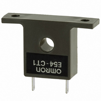
E54-CT1
Description
TRANSFORMER CURRNT 50A E5AK/E5CK
Manufacturer
Omron
Specifications of E54-CT1
Accessory Type
Current Transformer
Input Current
50A
Transformer Mounting
Chassis
Length/height, External
25mm
Output Current
50A
Transformer Type
Current
Current Rating
50A
Mounting Type
Chassis
Supply Voltage
1000 VoltsAC
Lead Free Status / RoHS Status
Lead free / RoHS Compliant
For Use With/related Products
E5AK/E5CK
Lead Free Status / Rohs Status
Lead free / RoHS Compliant
Other names
E54CT1
Z2416
Z2416


J Characteristics
Note: 1. The indication accuracy of the K, T, and N thermocouples at a temperature of -100°C or less is ±2°C ±1 digit maximum.
Indication accuracy
Hysteresis
Proportional band (P)
Integral (reset) time (I)
Derivative (rate) time (D)
Control period
Manual reset value
Alarm setting range
Sampling period
(See Note 3)
(See ote 3)
Insulation resistance
Dielectric strength
Vibration
resistance
Shock resistance
Ambient
t
temperature
Ambient humidity
Enclosure ratings
Memory protection
Weight
EMC
Approved standards
i t
2. The indication accuracy of the Pt at --100.0°C to 100.0°C is ±0.1% FS ±1 digit maximum.
3. The sampling period of the standard model with CT and remote SP inputs is 250 ms.
t
The indication accuracy of the B thermocouple at a temperature of 400°C or less is unrestricted.
The indication accuracy of the R and S thermocouples at a temperature of 200°C or less is ±3°C ±1 digit maximum.
The indication accuracy of the W thermocouple at any temperature is (±0.3% of the indicated value or ±3°C, whichever
is greater) ±1 digit maximum.
The indication accuracy of the PLII thermocouple at any temperature is (±0.3% or ±2°C, whichever is greater) ±1 digit
maximum.
g
Temperature
input
Analog input
Malfunction
Destruction
Malfunction
Destruction
Operating
Storage
Operating
Front panel
Rear case
Terminals
Thermocouple (See Note 1):
±0.3% of indication value or ±1°C, whichever greater, ±1 digit max.
Platinum resistance thermometer (See Note 2):
±0.2% of indication value or ±0.8°C, whichever greater, ±1 digit max.
Analog input: ±0.2% FS ±1 digit max.
0.01% to 99.99% FS (in units of 0.01% FS)
0.1% to 999.9% FS (in units of 0.1% FS)
0 to 3,999 s (in units of 1 s)
0 to 3,999 s (in units of 1 s)
1 to 99 s (in units of 1 s)
0.0% to 100.0% (in units of 0.1%)
--1,999 to 9,999 or --199.9 or 999.9 (decimal point position dependent on input type)
250 ms
100 ms
20 MΩ min. at 500 VDC
2,000 VAC, 50/60 Hz for 1 min between terminals of different polarities
10 to 55 Hz, 10 m/s
10 to 55 Hz, 20 m/s
200 m/s
(100 m/s
300 m/s
--10 to 55°C (14 to 131°F) with no icing/3-year warranty period: --10 to 50°C (14 to 122°F)
--25 to 65°C (--13 to 149°F) with no icing
35% to 85%
NEMA 4 for indoor use (equivalent to IP66)
IEC standard IP20
IEC standard IP00
Non-volatile memory (number of writings: 100,000 operations)
Approx. 320 g
Mounting bracket: approx. 65 g
Emission Enclosure:
Emission AC Mains:
Immunity ESD:
Immunity RF-interference:
Immunity Conducted Disturbance: ENV50141:
Immunity Burst:
UL1092, CSA22.2 No. 14, CSA22.2 No. 1010-1
Conforms to EN50081-2, EN50082-2, EN61010-1 (IEC61010-1)
Conforms to VDE0106/part 100 (Finger Protection), when the separately-ordered terminal
cover is mounted.
2
2
2
min. (approx. 20G), 3 times each in 6 directions
min. (approx. 30G), 3 times each in 6 directions
(approx. 10G) applied to the relay)
Process Controller with DeviceNet
2
2
(approx. 1G) for 10 min each in X, Y, and Z directions
(approx. 2G) for 2 hrs each in X, Y, and Z directions
EN55011 Group 1 class A
EN55011 Group 1 class A
EN61000-4-2: 4 kV contact discharge (level 2) 8 kV
ENV50140:
EN61000-4-4: 2 kV power-line (level 3)
air discharge (level 3)
10 V/m (amplitude modulated, 80 MHz
to 1 GHz) (level 3)
10 V/m (pulse modulated, 900 MHz)
10 V (0.15 to 80 MHz) (level 3)
2 kV I/O signal-line (level 4)
E5EK- -DRT
A--195