E5ZN-2TNH03TC-FLK Omron, E5ZN-2TNH03TC-FLK Datasheet - Page 11
E5ZN-2TNH03TC-FLK
Manufacturer Part Number
E5ZN-2TNH03TC-FLK
Description
CONTRLR TEMP MODULAR RS-485 NPN
Manufacturer
Omron
Series
E5ZNr
Type
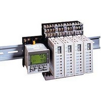
Temperature Controller, Modularr
Specifications of E5ZN-2TNH03TC-FLK
Output Type
Transistor
Supply Voltage
24VDC
Input Type
Thermocouple (Multiple)
Controller Type
On/Off or Proportional (PID)
Temperature Range
Selectable, Varies By Input Type
Size
DIN Rail Module
Features
DIN Rail Mount
Communications
RS-485 (CompoWay/F)
Display Type
LED Lights
Operating Temperature Max
55°C
Operating Temperature Min
-10°C
Temperature Accuracy ±
0.5%
Output Voltage Max
30VDC
Controller Output Type 1
Transistor
Mounting Type
DIN
Rohs Compliant
Yes
Thermocouple Type
J, K, T, E, L, U, N, R, S, B
Approval Bodies
CE / CSA / UL
Lead Free Status / RoHS Status
Lead free / RoHS Compliant
Lead Free Status / RoHS Status
Lead free / RoHS Compliant, Lead free / RoHS Compliant
Other names
E5ZN2TNH03TCFLK


Back-connecting Sockets
P3GA-11 (Standard Model)
Safety Precautions
Refer to Safety Precautions for All Temperature Controllers.
■ Safety Precautions
Observe the following points to ensure safe operation.
1. Use and store the product within the specified temperature and
2. Do not touch the electronic components or pattern of the PCB.
3. To ensure proper heat dissipation, leave a space around the
4. Use at the rated power supply voltage with the rated load.
5. Be sure to connect terminals with the correct polarity.
6. Perform wiring using crimp terminals of the specified size. (E5ZN-
7. Be sure to use wires satisfying the following specifications for
8. Do not connect anything to unused terminals.
9. Ensure that the rated voltage is reached within 2 seconds of
10.Allow 30 seconds’ warm-up time.
11.Install the product as far away as possible from devices that
12.Keep wiring separate from high-voltage power lines or power lines
Terminal Cover
Y92A-48G
Provide at least one power-interruption switch to
ensure that the power is OFF before wiring. Not
doing so may result in electric shock.
humidity ranges. Cool the product (e.g., using fans) where
necessary.
Hold the product by the case.
product. Do not block the product’s ventilating holes.
SCT@S-500: M3.0, width 5.8 mm max.; E5ZN-SDL: M3.5, width
7.2 max.)
connection using bare wires.
Power supply terminals: AWG 22 to 14
Other terminals: AWG 28 to 16
(Length of exposed part: 6 to 8 mm)
turning power ON.
generate strong, high-frequency noise and devices that generate
surges.
carrying large currents. Do not wire in parallel with or together
with power lines.
Note: Use in combination with a Terminal Cover (Y92A-
48G) for finger protection.
!WARNING
45
34
Y92A-48G
27 dia.
Twelve, 6.4 dia.
45
47.4
UP
P C
16.5
4.5
@47.7
24.6
16.3
27.6
25.6
6.2
@48
8.7
4
13.Install switches or circuit-breakers so that the user can turn the
14.Do not use the product in the following locations:
15.When the Terminal Unit is separated from the Temperature
16.Do not use solvents to clean the product. Use commercial
17.After wiring is completed remove the dust-protection label to allow
18.When mounting the Temperature Controller to the Terminal Unit,
19.Install the DIN track vertically.
7
power OFF immediately, and indicate these accordingly.
• Locations subject to dust or corrosive gases (in particular,
• Locations subject to freezing or condensation
• Locations exposed to direct sunlight
• Locations subject to vibrations or shocks
• Locations subject to exposure to water or oil
• Locations subject to heat radiated directly from heating
• Locations subject to intense temperature changes
Controller, under no circumstances touch the electrical
components or apply shock to the Temperature Controller.
alcohol.
proper heat dissipation.
make sure that the hook on the side of the Temperature Controller
facing the Terminal Unit is inserted properly.
sulfide gas and ammonia gas)
equipment
3
6
Terminal Arrangement/
Internal Connections
(BOTTOM VIEW)
4
3
5
2
6
1
11
7
10
8
9
E5ZN
11