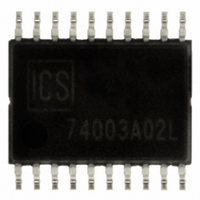
ICS874003AG-02LF IDT, Integrated Device Technology Inc, ICS874003AG-02LF Datasheet - Page 9

ICS874003AG-02LF
Manufacturer Part Number
ICS874003AG-02LF
Description
IC JITTER ATTENUATOR 20-TSSOP
Manufacturer
IDT, Integrated Device Technology Inc
Series
HiPerClockS™r
Type
Jitter Attenuatorr
Datasheet
1.ICS874003AG-02LF.pdf
(15 pages)
Specifications of ICS874003AG-02LF
Input
HCSL, LVDS, LVHSTL, LVPECL, SSTL
Output
LVDS
Frequency - Max
320MHz
Voltage - Supply
3.135 V ~ 3.465 V
Operating Temperature
0°C ~ 70°C
Mounting Type
Surface Mount
Package / Case
20-TSSOP
Frequency-max
320MHz
Number Of Elements
1
Supply Current
75mA
Pll Input Freq (min)
98MHz
Pll Input Freq (max)
128MHz
Operating Supply Voltage (typ)
3.3V
Operating Temp Range
0C to 70C
Package Type
TSSOP
Output Frequency Range
98 to 320MHz
Operating Supply Voltage (min)
3.015/3.135V
Operating Supply Voltage (max)
3.465V
Operating Temperature Classification
Commercial
Pin Count
20
Lead Free Status / RoHS Status
Lead free / RoHS Compliant
Other names
800-1214
800-1214-5
800-1214
874003AG-02LF
800-1214-5
800-1214
874003AG-02LF
ICS874003-02 Data Sheet
Differential Clock Input Interface
The CLK /nCLK accepts LVDS, LVPECL, LVHSTL, SSTL, HCSL and
other differential signals. The differential signal must meet the V
and V
examples for the CLK/nCLK input driven by the most common driver
types. The input interfaces suggested here are examples only.
Figure 3A.CLK/nCLK Input Driven by an IDT
Figure 3C. CLK/nCLK Input
Figure 3E. CLK/nCLK Input
ICS874003AG-02 REVISION B SEPTEMBER 14, 2010
Open Emitter LVHSTL Driver
CMR
3.3V
3.3V
HCSL
1.8V
LVPECL
input requirements. Figures 3A to 3F show interface
*Optional – R3 and R4 can be 0Ω
LVHSTL
IDT
LVHSTL Driver
Driven by a 3.3V LVPECL Driver
Driven by a 3.3V HCSL Driver
*R3
*R4
Zo = 50Ω
Zo = 50Ω
33Ω
33Ω
Zo = 50Ω
Zo = 50Ω
Zo = 50Ω
Zo = 50Ω
R3
125Ω
3.3V
R1
50Ω
R1
84Ω
R1
50Ω
R4
125Ω
R2
50Ω
R2
84Ω
R2
50Ω
CLK
nCLK
CLK
nCLK
CLK
nCLK
3.3V
3.3V
3.3V
Differential
Input
Differential
Input
Differential
Input
PP
9
Please consult with the vendor of the driver component to confirm the
driver termination requirements. For example, in Figure 3A, the input
termination applies for IDT open emitter LVHSTL drivers. If you are
using an LVHSTL driver from another vendor, use their termination
recommendation.
Figure 3B. CLK/nCLK Input
Figure 3D. CLK/nCLK Input
Figure 3F. CLK/nCLK Input
2.5V
3.3V
3.3V
LVDS
SSTL
LVPECL
Driven by a 3.3V LVPECL Driver
Driven by a 3.3V LVDS Driver
Driven by a 2.5V SSTL Driver
Zo = 60Ω
Zo = 60Ω
Zo = 50Ω
Zo = 50Ω
Zo = 50Ω
Zo = 50Ω
©2010 Integrated Device Technology, Inc.
PCI EXPRESS™ JITTER ATTENUATOR
R3
120Ω
2.5V
R1
120Ω
R1
50Ω
R2
50Ω
R4
120Ω
R2
120Ω
R2
50Ω
R1
100Ω
CLK
nCLK
CLK
nCLK
CLK
nCLK
3.3V
3.3V
3.3V
Differential
Input
Differential
Input
Receiver


