M48T02-150PC1 STMicroelectronics, M48T02-150PC1 Datasheet - Page 17
M48T02-150PC1
Manufacturer Part Number
M48T02-150PC1
Description
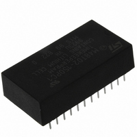
IC TIMEKPR NVRAM 16KBIT 5V 24-DI
Manufacturer
STMicroelectronics
Series
Timekeeper®r
Type
Clock/Calendar/NVSRAMr
Specifications of M48T02-150PC1
Memory Size
16K (2K x 8)
Time Format
HH:MM:SS (24 hr)
Date Format
YY-MM-DD-dd
Interface
Parallel
Voltage - Supply
4.75 V ~ 5.5 V
Operating Temperature
0°C ~ 70°C
Mounting Type
Through Hole
Package / Case
24-DIP (600 mil) Module
Function
Clock/Calendar/NV Timekeeping RAM/Battery Backup
Rtc Memory Size
2048 Byte
Supply Voltage (max)
5.5 V
Supply Voltage (min)
4.75 V
Maximum Operating Temperature
+ 70 C
Minimum Operating Temperature
0 C
Mounting Style
Through Hole
Rtc Bus Interface
Parallel
Capacitance, Input
10 pF
Capacitance, Output
10 pF
Current, Input, Leakage
±1 μA
Current, Operating
80 mA
Current, Output, Leakage
±1
Data Retention
10 yrs.
Density
16K
Memory Type
Non-Volatile SRAM
Organization
2K×8
Package Type
PCDIP24
Power Dissipation
1 W
Temperature, Operating
0 to +70 °C
Time, Access
150 ns
Time, Fall
≤5 ns
Time, Rise
≤5 ns
Voltage, Input, High
5.05 to 5.8 V
Voltage, Input, Low
0.8 V
Voltage, Output, High
2.4 V
Voltage, Output, Low
0.4 V
Voltage, Supply
4.75 to 5.5 V
Lead Free Status / RoHS Status
Lead free / RoHS Compliant
Other names
497-2825-5
Available stocks
Company
Part Number
Manufacturer
Quantity
Price
Company:

Part Number:
M48T02-150PC1
Manufacturer:
Maxim
Quantity:
58
Part Number:
M48T02-150PC1
Manufacturer:
ST
Quantity:
20 000


M48T02, M48T12
4
Caution:
Maximum ratings
Stressing the device above the rating listed in the absolute maximum ratings table may
cause permanent damage to the device. These are stress ratings only and operation of the
device at these or any other conditions above those indicated in the operating sections of
this specification is not implied. Exposure to absolute maximum rating conditions for
extended periods may affect device reliability.
Table 6.
1. Soldering temperature of the IC leads is to not exceed 260 °C for 10 seconds. In order to protect the lithium
2. For DIP packaged devices, ultrasonic vibrations should not be used for post-solder cleaning to avoid
Negative undershoots below –0.3 V are not allowed on any pin while in the battery backup
mode.
T
Symbol
battery, preheat temperatures must be limited such that the battery temperature does not exceed +85 °C.
Furthermore, the devices shall not be exposed to IR reflow.
damaging the crystal.
SLD
T
V
V
P
T
STG
I
CC
O
IO
A
D
(1)(2)
Absolute maximum ratings
Ambient operating temperature
Storage temperature (V
Lead solder temperature for 10 seconds
Input or output voltages
Supply voltage
Output current
Power dissipation
Doc ID 2410 Rev 8
Parameter
CC
off, oscillator off)
–40 to 85
–0.3 to 7
–0.3 to 7
0 to 70
Value
260
20
1
Maximum ratings
Unit
mA
°C
°C
°C
W
V
V
17/25
Related parts for M48T02-150PC1
Image
Part Number
Description
Manufacturer
Datasheet
Request
R

Part Number:
Description:
IC TIMEKPR NVRAM 16KBIT 5V 24-DI
Manufacturer:
STMicroelectronics
Datasheet:

Part Number:
Description:
5.0V, 16 Kbit (2Kb x 8) TIMEKEEPER� SRAM
Manufacturer:
STMICROELECTRONICS [STMicroelectronics]
Datasheet:
Part Number:
Description:
IC TIMEKPR NVRAM 16KBIT 5V 24-DI
Manufacturer:
STMicroelectronics
Datasheet:

Part Number:
Description:
STMicroelectronics [RIPPLE-CARRY BINARY COUNTER/DIVIDERS]
Manufacturer:
STMicroelectronics
Datasheet:
Part Number:
Description:
STMicroelectronics [LIQUID-CRYSTAL DISPLAY DRIVERS]
Manufacturer:
STMicroelectronics
Datasheet:

Part Number:
Description:
BOARD EVAL FOR MEMS SENSORS
Manufacturer:
STMicroelectronics
Datasheet:
Part Number:
Description:
NPN TRANSISTOR POWER MODULE
Manufacturer:
STMicroelectronics
Datasheet:
Part Number:
Description:
TURBOSWITCH ULTRA-FAST HIGH VOLTAGE DIODE
Manufacturer:
STMicroelectronics
Datasheet:
Part Number:
Description:
Manufacturer:
STMicroelectronics
Datasheet:
Part Number:
Description:
DIODE / SCR MODULE
Manufacturer:
STMicroelectronics
Datasheet:
Part Number:
Description:
DIODE / SCR MODULE
Manufacturer:
STMicroelectronics
Datasheet: