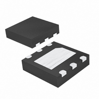
DS1375T+T&R Maxim Integrated Products, DS1375T+T&R Datasheet - Page 6

DS1375T+T&R
Manufacturer Part Number
DS1375T+T&R
Description
IC RTC SERIAL W/ALARM 6TDFN
Manufacturer
Maxim Integrated Products
Type
Clock/Calendar/Alarmr
Datasheet
1.DS1375T.pdf
(13 pages)
Specifications of DS1375T+T&R
Time Format
HH:MM:SS (12/24 hr)
Date Format
YY-MM-DD-dd
Interface
I²C, 2-Wire Serial
Voltage - Supply
1.7 V ~ 5.5 V
Operating Temperature
-40°C ~ 85°C
Mounting Type
Surface Mount
Package / Case
6-TDFN Exposed Pad
Lead Free Status / RoHS Status
Lead free / RoHS Compliant
Memory Size
-
I
The DS1375 digital input RTC with alarm is a low-power
clock/calendar with two programmable time-of-day
alarms and a programmable square-wave output.
Address and data are transferred serially through the
I
seconds, minutes, hours, day, date, month, and year
information. The date at the end of the month is auto-
matically adjusted for months with fewer than 31 days,
including corrections for leap year. The clock operates
in either the 24-hour or 12-hour format with an AM/PM
indicator. The DS1375 requires an external clock
source selectable between 32,768Hz, 8192Hz, 60Hz,
or 50Hz for the timekeeping function. Sixteen bytes of
SRAM are provided for additional user storage.
When power is applied, the time and date registers are
reset to 01/01/00 01 00:00:00 (MM/DD/YY DOW
HH:MM:SS).
The DS1375 operates as a slave device on the serial
bus. Access is obtained by implementing a START
condition and providing a device identification code,
followed by data. Subsequent registers can be
accessed sequentially until a STOP condition is execut-
ed. The functional diagram in Figure 2 shows the main
elements of the serial RTC.
6
2
2
C serial interface bus. The clock/calendar provides
C Digital Input RTC with Alarm
_____________________________________________________________________
PIN
—
1
2
3
4
5
6
SQW/
NAME
GND
CLK
SDA
SCL
V
EP
CC
Detailed Description
Digital Clock Input. This pin must be 32,768Hz, 8192Hz, 60Hz, or 50Hz square wave, 45% to 55%
duty cycle.
Square-Wave/Interrupt Output. This pin is open drain and requires an external pullup resistor. The
pullup voltage can be up to 5.5V, regardless of the voltage on V
Ground
Serial Data Input/Output. SDA is the data input/output for the I
and requires an external pullup resistor. The pullup voltage can be up to 5.5V, regardless of the
voltage on V
Serial Clock Input. SCL is the clock input for the I
data movement on the serial interface. Up to 5.5V can be used for this pin, regardless of the
voltage on V
DC Power for Primary Power Supply
Exposed Pad. Can be connected to ground.
CC
CC
Operation
.
.
Table 1 shows the address map for the timekeeping
registers and SRAM. The 16 bytes of SRAM occupy
addresses 10h–1Fh. During a multibyte access, when
the address pointer reaches the end of the register
space (1Fh), it wraps around to location 00h. On a
I
location 00h, the current time is transferred to a second
set of registers. The time information is read from these
secondary registers, while the clock may continue to
run. This eliminates the need to reread the registers in
case the main registers update during a read.
Note: Unless otherwise specified, the state of the regis-
ters is not defined when power is first applied.
The time and calendar information is obtained by read-
ing the appropriate register bytes. Table 1 shows the
RTC registers. The time and calendar data are set or
initialized by writing the appropriate register bytes. The
contents of the time and calendar registers are in the
binary-coded decimal (BCD) format. The DS1375 can
be run in either 12-hour or 24-hour mode. Bit 6 of the
hours register is defined as the 12- or 24-hour mode
select bit. When high, the 12-hour mode is selected. In
the 12-hour mode, bit 5 is the AM/PM bit with logic high
being PM. In the 24-hour mode, bit 5 is the second 10-
hour bit (20–23 hours). The century bit (bit 7 of the
2
C START, STOP, or address pointer incrementing to
FUNCTION
2
C serial interface, and is used to synchronize
2
C serial interface. It is open drain
CC
Clock and Calendar
.
Pin Description
Address Map


