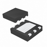
DS1375T+T&R Maxim Integrated Products, DS1375T+T&R Datasheet

DS1375T+T&R
Specifications of DS1375T+T&R
Related parts for DS1375T+T&R
DS1375T+T&R Summary of contents
Page 1
... Operation PART DS1375T+ + Denotes a lead-free/RoHS-compliant package Exposed pad. TOP VIEW CLK V BAT V CC SQW/INT GND DS32kHz GND *EXPOSED PAD ______________________________________________ Maxim Integrated Products Features 2 C Interface Ordering Information TEMP RANGE PIN-PACKAGE TOP MARK -40°C to +85°C 6 TDFN-EP* DS1375 Pin Configuration + ...
Page 2
I C Digital Input RTC with Alarm ABSOLUTE MAXIMUM RATINGS Voltage Range on V Pin CC Relative to Ground.............................................-0.3V to +6.0V Voltage Range on SDA, SCL, and WDS Relative to Ground ....................................-0. Operating Temperature Range ...........................-40°C to ...
Page 3
AC ELECTRICAL CHARACTERISTICS ( -40°C to +85°C, unless otherwise noted.) (Note 1, Figure 1) CC CCMIN CCMAX A PARAMETER SYMBOL SCL Clock Frequency Bus Free Time Between STOP and START Conditions Hold Time ...
Page 4
I C Digital Input RTC with Alarm SDA t BUF t LOW SCL t HD:STA STOP START 2 Figure 1. Data Transfer Serial Bus CLK DIVIDER DS1375 SCL SERIAL BUS INTERFACE AND ADDRESS REGISTER SDA Figure ...
Page 5
T = +25°C, unless otherwise noted vs. V CCS 300 250 200 150 100 50 1.7 2.2 2.7 3.2 3 vs. TEMPERATURE CCS 135.0 132.5 V 130.0 127.5 125.0 122.5 ...
Page 6
I C Digital Input RTC with Alarm PIN NAME Digital Clock Input. This pin must be 32,768Hz, 8192Hz, 60Hz, or 50Hz square wave, 45% to 55% 1 CLK duty cycle. Square-Wave/Interrupt Output. This pin is open drain and requires ...
Page 7
Table 1. Timekeeping Registers and SRAM ADDRESS BIT 7 BIT 6 BIT 5 00h 0 10 Seconds 01h 0 10 Minutes AM/PM 02h 0 12/24 10 Hours 03h 0 0 04h 0 0 05h Century 0 06h 10 Year 07h ...
Page 8
I C Digital Input RTC with Alarm The DS1375 contains two time-of-day/date alarms. Alarm 1 can be set by writing to registers 07h–0Ah. Alarm 2 can be set by writing to registers 0Bh–0Dh. The alarms can be programmed (by ...
Page 9
Bit 7 Bit 6 Bit 5 ECLK CLKSEL1 CLKSEL0 Control Register (0Eh) Bit 7/Enable Clock (ECLK). When ECLK is set to logic 1, the CLK input pin is enabled to clock the internal divider chain and advance the timekeeping registers. ...
Page 10
I C Digital Input RTC with Alarm Bit 7 Bit 6 Bit Status Register (0Fh) Bit 1/Alarm 2 Flag (A2F). A logic 1 in the alarm 2 flag bit indicates that the time matched the alarm ...
Page 11
There is one clock pulse per bit of data. Each data transfer is initiated with a START condi- tion and terminated with a STOP condition. The number of data bytes transferred between ...
Page 12
I C Digital Input RTC with Alarm <SLAVE ADDRESS> <R/W> <WORD ADDRESS (n)> S 1101000 0 A XXXXXXXX S - START SLAVE TO MASTER A - ACKNOWLEDGE (ACK STOP R/W - READ/WRITE OR DIRECTION BIT ADDRESS Figure ...
Page 13
... Maxim cannot assume responsibility for use of any circuitry other than circuitry entirely embodied in a Maxim product. No circuit patent licenses are implied. Maxim reserves the right to change the circuitry and specifications without notice at any time. Maxim Integrated Products, 120 San Gabriel Drive, Sunnyvale, CA 94086 408-737-7600 ____________________ 13 © 2008 Maxim Integrated Products is a registered trademark of Dallas Semiconductor Corporation ...


