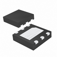
DS1375T+T&R Maxim Integrated Products, DS1375T+T&R Datasheet - Page 7

DS1375T+T&R
Manufacturer Part Number
DS1375T+T&R
Description
IC RTC SERIAL W/ALARM 6TDFN
Manufacturer
Maxim Integrated Products
Type
Clock/Calendar/Alarmr
Datasheet
1.DS1375T.pdf
(13 pages)
Specifications of DS1375T+T&R
Time Format
HH:MM:SS (12/24 hr)
Date Format
YY-MM-DD-dd
Interface
I²C, 2-Wire Serial
Voltage - Supply
1.7 V ~ 5.5 V
Operating Temperature
-40°C ~ 85°C
Mounting Type
Surface Mount
Package / Case
6-TDFN Exposed Pad
Lead Free Status / RoHS Status
Lead free / RoHS Compliant
Memory Size
-
month register) is toggled when the years register over-
flows from 99 to 00.
The day-of-week register increments at midnight.
Values that correspond to the day of week are user-
defined but must be sequential (i.e., if 1 equals
Sunday, then 2 equals Monday, and so on). Illogical
time and date entries result in undefined operation.
When reading or writing the time and date registers,
secondary (user) buffers are used to prevent errors
when the internal registers update. When reading the
time and date registers, the user buffers are synchro-
nized to the internal registers on any START or STOP
Table 1. Timekeeping Registers and SRAM
ADDRESS
10h–1Fh
0Ah
0Bh
0Ch
0Dh
00h
01h
02h
03h
04h
05h
06h
07h
08h
09h
0Eh
0Fh
Century
A1M1
A1M2
A1M3
A1M4
A2M2
A2M3
A2M4
ECLK
BIT 7
B7
0
0
0
0
0
0
CLKSEL1 CLKSEL0
DY/DT
DY/DT
BIT 6
12/24
12/24
12/24
B6
0
0
0
0
10 Year
10 Seconds
10 Seconds
10 Minutes
10 Minutes
10 Minutes
10 Hours
10 Hours
10 Hours
AM/PM
AM/PM
AM/PM
BIT 5
B5
0
0
0
10 Date
10 Date
10 Date
I
_____________________________________________________________________
2
—
10 Hours
10 Hours
10 Hours
C Digital Input RTC with Alarm
BIT 4
Month
RS2
10
B4
0
0
BIT 3
RS1
B3
0
0
INTCN
BIT 2
and when the register pointer rolls over to zero. The
time information is read from these secondary registers,
while the clock continues to run. This eliminates the
need to reread the registers in case the main registers
update during a read.
The countdown chain is reset whenever the seconds
register is written. Write transfers occur on the acknowl-
edge from the DS1375. Once the countdown chain is
reset, to avoid rollover issues the remaining time and
date registers must be written within 1 second. The 1Hz
square-wave output, if enabled, transitions high 500ms
after the seconds data transfer, provided the clock
input is already being driven.
B2
0
Seconds
Seconds
Minutes
Minutes
Minutes
Months
Hours
Hours
Hours
Date
Year
Date
Date
Day
Day
BIT 1
A2IE
Day
A2F
B1
BIT 0
A1IE
A1F
B0
Alarm 1 Seconds
Alarm 1 Minutes
Alarm 2 Minutes
Alarm 1 Hours
Alarm 2 Hours
Alarm 1 Date
Alarm 2 Date
Alarm 1 Day
Alarm 2 Day
FUNCTION
Seconds
Minutes
Century
Control/
Control
Month/
Hours
Status
SRAM
Date
Year
Day
1–12 + AM/PM
1–12 + AM/PM
1–12 + AM/PM
RANGE
01–12 +
Century
00–FFH
00–59
00–59
00–23
00–31
00–99
00–59
00–59
00–23
00–59
00–23
1–31
1–31
1–7
1–7
1–7
—
—
7


