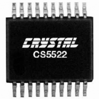
CS5522-ASZ Cirrus Logic Inc, CS5522-ASZ Datasheet - Page 29

CS5522-ASZ
Manufacturer Part Number
CS5522-ASZ
Description
IC ADC 24BIT SIG/DELT 20-SSOP
Manufacturer
Cirrus Logic Inc
Specifications of CS5522-ASZ
Number Of Converters
1
Package / Case
20-SSOP
Number Of Bits
24
Data Interface
Serial
Power Dissipation (max)
14.8mW
Voltage Supply Source
Analog and Digital
Operating Temperature
-40°C ~ 85°C
Mounting Type
Surface Mount
Number Of Adc Inputs
1
Architecture
Delta-Sigma
Conversion Rate
617 SPs
Resolution
24 bit
Input Type
Voltage
Interface Type
Serial (3-Wire)
Voltage Reference
2.5 V
Supply Voltage (max)
5 V
Supply Voltage (min)
25 mV
Maximum Power Dissipation
500 mW
Maximum Operating Temperature
+ 85 C
Mounting Style
SMD/SMT
Input Voltage
25 mV to 5 V
Minimum Operating Temperature
- 40 C
Package
20SSOP
Sampling Rate
0.617 KSPS
Number Of Adcs
1
Number Of Analog Inputs
2
Digital Interface Type
Serial (3-Wire, SPI, Microwire)
Polarity Of Input Voltage
Unipolar|Bipolar
Lead Free Status / RoHS Status
Lead free / RoHS Compliant
Lead Free Status / RoHS Status
Lead free / RoHS Compliant, Lead free / RoHS Compliant
Other names
598-1104-5
Available stocks
Company
Part Number
Manufacturer
Quantity
Price
Part Number:
CS5522-ASZ
Manufacturer:
CIRRUS
Quantity:
20 000
CS5522/24/28 typically consume 9.0 mW. The
CS5521/23 typically consume 6.0 mW. The low-
power mode is an alternate mode in the
CS5522/24/28 that reduces the consumed power to
5.5 mW. It is entered by setting bit D8 (the low-
power mode bit) in the configuration register to
logic 1. Slightly degraded noise or linearity perfor-
mance should be expected in the low-power mode.
Note that the XIN clock should not exceed 130 kHz
in low-power mode. The final two modes accom-
modated in all devices are referred to as the power
save modes. They power down most of the analog
portion of the chip and stop filter convolutions. The
power-save modes are entered whenever the PS/R
bit of the configuration register is set to logic 1. The
particular power-save mode entered depends on
state of bit D11 (PSS, the Power Save Select bit) in
the configuration register. If PSS is logic 0, the
converters enters the standby mode reducing the
power consumption to 1.2 mW. The standby mode
leaves the oscillator and the on-chip bias generator
running. This allows the converter to quickly return
to the normal or low-power mode once the PS/R bit
is set back to a logic 0. If PSS and PS/R in the con-
figuration register are set to logic 1, the sleep mode
is entered reducing the consumed power to around
500 µW. Since the sleep mode disables the oscilla-
tor, approximately a 500ms oscillator start-up de-
lay period is required before returning to the
normal or low-power mode.
2.2.8.4 Charge Pump Disable
The pump disable (PD) bit permits the user to turn
off the charge pump drive thus enabling the user to
reduce the radiation of digital interference from the
CPD pin when the charge pump is not being used.
2.2.8.5 Reset System Control Bits
The reset system (RS) bit permits the user to per-
form a system reset. A system reset can be initiated
at any time by writing a logic 1 to the RS bit in the
DS317F4
configuration register. After a system reset cycle is
complete, the reset valid (RV) bit is set indicating
that the internal logic was properly reset. The RV
remains set until the configuration register is read.
Note that the user must write a logic 0 to the RS bit
to take the part out of the reset mode. No other bits
in the configuration register can be written at this
time. A subsequent write to the configuration reg-
ister is necessary to write to any other bits in this
register. Once reset, the on-chip registers are ini-
tialized to the following states.
2.2.8.6 Data Conversion Error Flags
The oscillation detect (OD) and overflow (OF) bits
in the configuration register are flag bits used to in-
dicate that the ADC performed a conversion on an
input signal that was not within the conversion
range of the ADC. For convenience, the OD and
OF bits are also in the data conversion word of the
CS5521/23.
The OF bit is set to logic 1 when the input signal is:
1) more positive than full scale
2) more negative than zero in unipolar mode, or
3) more negative than negative full scale in bipo-
The OF flag is cleared to logic 0 when a conversion
occurs which is not out of range.
The OD bit is set to logic 1 any time that an oscil-
latory condition is detected in the modulator. This
does not occur under normal operating conditions,
but may occur when the input is extremely over-
ranged. The OD flag will be cleared to logic 0 when
the modulator becomes stable.
configuration register:
offset registers:
gain registers:
channel setup registers:
lar mode.
CS5521/22/23/24/28
000040(H)
000000(H)
400000(H)
000000(H)
29


