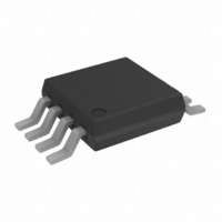
AD7450ARMZ Analog Devices Inc, AD7450ARMZ Datasheet - Page 14

AD7450ARMZ
Manufacturer Part Number
AD7450ARMZ
Description
IC ADC 12BIT DIFF IN 1MSPS 8MSOP
Manufacturer
Analog Devices Inc
Datasheet
1.AD7450ARMZ.pdf
(20 pages)
Specifications of AD7450ARMZ
Data Interface
DSP, MICROWIRE™, QSPI™, Serial, SPI™
Number Of Bits
12
Sampling Rate (per Second)
1M
Number Of Converters
1
Power Dissipation (max)
9.25mW
Voltage Supply Source
Single Supply
Operating Temperature
-40°C ~ 85°C
Mounting Type
Surface Mount
Package / Case
8-TSSOP, 8-MSOP (0.118", 3.00mm Width)
Resolution (bits)
12bit
Input Channel Type
Differential
Supply Voltage Range - Analogue
2.7V To 3.3V, 4.75V To 5.25V
Supply Current
1.8mA
No. Of Pins
8
Operating
RoHS Compliant
Sampling Rate
1MSPS
Rohs Compliant
Yes
Lead Free Status / RoHS Status
Lead free / RoHS Compliant
For Use With
EVAL-AD7450CBZ - BOARD EVALUATION FOR AD7450
Lead Free Status / RoHS Status
Lead free / RoHS Compliant
Available stocks
Company
Part Number
Manufacturer
Quantity
Price
Part Number:
AD7450ARMZ
Manufacturer:
ADI/亚德诺
Quantity:
20 000
AD7450
The circuit configuration shown in Figure 15b converts a unipolar,
single-ended signal into a differential signal.
RF Transformer
In systems that do not need to be dc-coupled, an RF transformer
with a center tap offers a good solution for generating differential
inputs. Figure 16 shows how a transformer is used for single-
ended-to-differential conversion. It provides the benefits of
operating the ADC in the differential mode without contributing
additional noise and distortion. An RF transformer also has the
benefit of providing electrical isolation between the signal source
and the ADC. A transformer can be used for most ac applications.
The center tap is used to shift the differential signal to the
common-mode level required. In this case, it is connected to the
reference so the common-mode level is the value of the reference.
REFERENCES SECTION
An external reference source is required to supply the reference to the
AD7450. This reference input can range from 100 mV to 3.5 V. With
a 5 V power supply, the specified reference is 2.5 V and the maximum
reference is 3.5 V. With a 3.3 V power supply, the specified refer-
ence is 1.25 V and the maximum reference is 2.4 V. In both cases,
the reference is functional from 100 mV. It is important to ensure
that, when choosing the reference value for a particular application,
the maximum analog input range (V
V
following two examples calculate the maximum V
used when operating the AD7450 at V
DD
VREF
GND
+ 0.3 V to comply with the maximum ratings of the part. The
Figure 16. Using an RF Transformer to Generate
Differential Inputs
Figure 15b. Dual Op Amp Circuit to Convert a
Single-Ended Unipolar Input into a Differential Input
2
R
V
REF
p-p
390
A
R
R
220
220
220
C
V+
V–
V+
V–
DD
IN
of 5 V and 3.3 V, respectively.
10k
max) is never greater than
3.75V
1.25V
2.5V
3.75V
2.5V
1.25V
V
V
IN+
27
27
IN–
REF
EXTERNAL
V
AD7450
REF
input that can be
V
V
V
REF
IN–
(2.5V)
IN+
EXTERNAL
AD7450
V
V
V
DD
REF
REF
0.1 F
–14–
Example 1:
Therefore, when operating at V
range from 100 mV to a maximum value of 3.5 V. When V
4.75 V, V
Example 2:
Therefore, when operating at V
can range from 100 mV to a maximum value of 2.4 V. When
V
These examples show that the maximum reference applied to
the AD7450 is directly dependant on the value of V
The performance of the part at different reference values is shown
in TPC 8 to TPC 12 and in TPC 15. The value of the reference
sets the analog input span and the common-mode voltage range.
Errors in the reference source will result in gain errors in the
AD7450 transfer function and will add to specified full-scale errors
on the part. A capacitor of 0.1 µF should be used to decouple
the V
references to be used that are available from Analog Devices, and
Figure 17 shows a typical connection diagram for the V
Reference
AD589
AD1580
REF192
REF43
AD780
V
*ADDITIONAL PINS OMITTED FOR CLARITY
Figure 17. Typical V
DD
DD
V
V
V
V
V
V
0.1 F
ThenV
Therefore
ThenV
Therefore
If V
If V
IN
IN
REF
IN
IN
REF
= 2.7 V, V
REF
Table I. Examples of Suitable Voltage References
max
max =
max
max =
DD
DD
max
max
pin to GND. Table I lists examples of suitable voltage
IN
IN
REF
= 5
= 3 3 .
10nF
=
=
max
max
3
3
= 3 5
= 2 4
V
V
V
V
max = 3.37 V.
V
Output
Voltage
1.235
1.225
2.5
2.5
2.5
×
×
DD
REF
DD
REF
REF
V
V
V
.
.
= 5 3
= 3 6
REF
REF
0.1 F
+ 0 3
+ 0 3
V
V
+
+
max = 2 V.
.
.
V
V
.
.
2 5 3
2
REF
REF
V
V
REF
NC
= .
= .
Initial
Accuracy (% Max)
1.2–2.8
0.08–0.8
0.08–0.4
0.06–0.1
0.04–0.2
3 6
Connection Diagram for V
2
2
NC = NO CONNECT
1
2
3
4
TEMP
GND
V
V
V
IN
DD
DD
AD780
O/P SEL
= 5 V, the value of V
= 3.3 V, the value of V
V
TRIM
OUT
8
7
6
5
NC
NC
NC
2.5V
Operating
Current ( A)
50
50
45
600
1000
DD
AD7450*
.
DD
REF
REF
REV. 0
REF
V
= 5 V
V
DD
REF
can
DD
pin.
0.1 F
=


