AD673JD Analog Devices Inc, AD673JD Datasheet - Page 4
AD673JD
Manufacturer Part Number
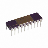
AD673JD
Description
IC ADC 8BIT W/REF/CLK/COMP 20DIP
Manufacturer
Analog Devices Inc
Datasheet
1.AD673JNZ.pdf
(8 pages)
Specifications of AD673JD
Rohs Status
RoHS non-compliant
Number Of Bits
8
Sampling Rate (per Second)
33k
Data Interface
Parallel
Number Of Converters
1
Voltage Supply Source
Dual ±
Operating Temperature
0°C ~ 70°C
Mounting Type
Through Hole
Package / Case
20-CDIP (0.300", 7.62mm)
Available stocks
Company
Part Number
Manufacturer
Quantity
Price


AD673
Full-Scale Calibration
The 5 k thin-film input resistor is laser trimmed to produce a
current which matches the full-scale current of the internal
DAC-plus about 0.3%—when an analog input voltage of 9.961
volts (10 volts – 1 LSB) is applied at the input. The input resis-
tor is trimmed in this way so that if a fine trimming potentio-
meter is inserted in series with the input signal, the input
current at the full scale input voltage can be trimmed down to
match the DAC full-scale current as precisely as desired. How-
ever, for many applications the nominal 9.961 volt full scale can
be achieved to sufficient accuracy by simply inserting a 15
sistor in series with the analog input to Pin 14. Typical full-scale
calibration error will then be within 2 LSB or 0.8%. If
more precise calibration is desired, a 200
used instead. Set the analog input at 9.961 volts, and set the
trimmer so that the output code is just at the transition between
111111 10 and 11111111. Each LSB will then have a weight of
39.06 mV. If a nominal full scale of 10.24 volts is desired
(which makes the LSB have a weight of exactly 40.0 mV), a
100
good resolution) should be used. Of course, larger full-scale
ranges can be arranged by using a larger input resistor, but lin-
earity and full-scale temperature coefficient may be compro-
mised if the external resistor becomes a sizeable percentage of
5 k Figure 3 illustrates the connections required for full-scale
calibration.
Unipolar Offset Calibration
Since the Unipolar Offset is less than 1/2 LSB for all versions
of the AD673, most applications will not require trimming. Fig-
ure 4 illustrates two trimming methods which can be used if
greater accuracy is necessary.
resistor and a 100
Figure 3. Standard AD673 Connections
Figure 4a.
Figure 4. Unipolar Offset Trimming
trimmer (or a 200
trimmer should be
Figure 4b.
trimmer with
re-
–4–
Figure 4a shows how the converter zero may be offset to correct
for initial offset and/or input signal offsets. As shown, the circuit
gives approximately symmetrical adjustment in unipolar mode.
Figure 5 shows the nominal transfer curve near zero for an
AD673 in unipolar mode. The code transitions are at the edges
of the nominal bit weights. In some applications it will be prefer-
able to offset the code transitions so that they fall between the
nominal bit weights, as shown in the offset characteristics.
This offset can easily be accomplished as shown in Figure 4b. At
balance (after a conversion) approximately 2 mA flows into the
Analog Common terminal. A 10
terminal will result in approximately the desired l/2 bit offset of
the transfer characteristics. The nominal 2 mA Analog Common
current is not closely controlled in manufacture. If high accuracy
is required, a 20
be used as R1. Additional negative offset range may be obtained
by using larger values of R1. Of course, if the zero transition
point is changed, the full-scale transition point will also move.
Thus, if an offset of 1/2 LSB is introduced, full scale trimming
as described on the previous page should be done with an analog
input of 9.941 volts.
NOTE: During a conversion, transient currents from the Analog
Common terminal will disturb the offset voltage. Capacitive
decoupling should not be used around the offset network. These
transients will settle appropriately during a conversion. Capaci-
tive decoupling will “pump up” and fail to settle resulting in
conversion errors. Power supply decoupling, which returns to
analog signal common, should go to the signal input side of the
resistive offset network.
Figure 5. AD673 Transfer Curve—Unipolar Operation
(Approximate Bit Weights Shown for Illustration,
Nominal Bit Weights % 39.06 mV)
potentiometer (connected as a rheostat) can
resistor in series with this
REV. A
Related parts for AD673JD
Image
Part Number
Description
Manufacturer
Datasheet
Request
R

Part Number:
Description:
±1.7g Dual-Axis IMEMS Accelerometer Evaluation Board
Manufacturer:
Analog Devices Inc
Datasheet:

Part Number:
Description:
Inertial Sensor Evaluation System
Manufacturer:
Analog Devices Inc
Datasheet:
Part Number:
Description:
Manufacturer:
Analog Devices Inc
Datasheet:
Part Number:
Description:
Manufacturer:
Analog Devices Inc
Datasheet:
Part Number:
Description:
Manufacturer:
Analog Devices Inc
Datasheet:
Part Number:
Description:
Manufacturer:
Analog Devices Inc
Datasheet:
Part Number:
Description:
Manufacturer:
Analog Devices Inc
Datasheet:
Part Number:
Description:
Manufacturer:
Analog Devices Inc
Datasheet:
Part Number:
Description:
Manufacturer:
Analog Devices Inc
Datasheet:
Part Number:
Description:
Manufacturer:
Analog Devices Inc
Datasheet:
Part Number:
Description:
Manufacturer:
Analog Devices Inc
Datasheet:
Part Number:
Description:
Manufacturer:
Analog Devices Inc
Datasheet:
Part Number:
Description:
Manufacturer:
Analog Devices Inc
Datasheet: