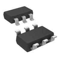
DAC101C081CIMK/NOPB National Semiconductor, DAC101C081CIMK/NOPB Datasheet - Page 19

DAC101C081CIMK/NOPB
Manufacturer Part Number
DAC101C081CIMK/NOPB
Description
DAC 10BIT MICROPWR I2C TSOT23-6
Manufacturer
National Semiconductor
Datasheet
1.DAC101C081CISDNOPB.pdf
(24 pages)
Specifications of DAC101C081CIMK/NOPB
Settling Time
3µs
Number Of Bits
10
Data Interface
I²C, Serial
Number Of Converters
1
Voltage Supply Source
Single Supply
Power Dissipation (max)
730µW
Operating Temperature
-40°C ~ 125°C
Mounting Type
Surface Mount
Package / Case
TSOT-23-6, TSOT-6
For Use With
DAC101C08XEB - BOARD EVALUATION FOR DAC101C08X
Lead Free Status / RoHS Status
Lead free / RoHS Compliant
Other names
DAC101C081CIMK
DAC101C081CIMK
DAC101C081CIMKTR
DAC101C081CIMK
DAC101C081CIMKTR
Available stocks
Company
Part Number
Manufacturer
Quantity
Price
Company:
Part Number:
DAC101C081CIMK/NOPB
Manufacturer:
TI
Quantity:
2 100
2.0 Applications Information
2.1 USING REFERENCES AS POWER SUPPLIES
While the simplicity of the DAC081C081 implies ease of use,
it is important to recognize that the path from the reference
input (V
to V
Ratio (PSRR). Therefore, it is necessary to provide a noise-
free supply voltage to the reference. In order to use the full
dynamic range of the DAC081C085, the supply pin (V
V
voltage. Since the DAC081C081 consumes very little power,
a reference source may be used as the supply voltage. The
advantages of using a reference source over a voltage regu-
lator are accuracy and stability. Some low noise regulators
can also be used. Listed below are a few reference and power
supply options for the DAC081C081. When using the
DAC081C081, it is important to treat the analog supply (V
as the reference.
2.1.1 LM4132
The LM4132, with its 0.05% accuracy over temperature, is a
good choice as a reference source for the DAC081C081. The
4.096V version is useful if a 0 to 4.095V output range is de-
sirable or acceptable. Bypassing the LM4132 V
0.1µF capacitor and the V
improve stability and reduce output noise. The LM4132
comes in a space-saving 5-pin SOT23.
REF
OUT
can be connected together and share the same supply
FIGURE 10. The LM4132 as a power supply
A
will have essentially zero Power Supply Rejection
for the DAC081C081 & V
OUT
pin with a 2.2µF capacitor will
REF
for the DAC081C085)
IN
pin with a
30052313
A
) and
A
)
19
2.1.2 LM4050
Available with accuracy of 0.44%, the LM4050 shunt refer-
ence is also a good choice as a reference for the
DAC081C081. It is available in 4.096V and 5V versions and
comes in a space-saving 3-pin SOT23.
The minimum resistor value in the circuit of Figure 11 must
be chosen such that the maximum current through the
LM4050 does not exceed its 15 mA rating. The conditions for
maximum current include the input voltage at its maximum,
the LM4050 voltage at its minimum, and the DAC081C081
drawing zero current. The maximum resistor value must allow
the LM4050 to draw more than its minimum current for regu-
lation plus the maximum DAC081C081 current in full opera-
tion. The conditions for minimum current include the input
voltage at its minimum, the LM4050 voltage at its maximum,
the resistor value at its maximum due to tolerance, and the
DAC081C081 draws its maximum current. These conditions
can be summarized as
and
where V
voltages ± the LM4050 output tolerance over temperature, I
(max) is the maximum allowable current through the LM4050,
I
proper
DAC081C081 supply current.
Z
(min) is the minimum current required by the LM4050 for
R(max) = ( V
FIGURE 11. The LM4050 as a power supply
Z
regulation,
(min) and V
R(min) = ( V
IN
(min) − V
Z
and
(max) are the nominal LM4050 output
IN
(max) − V
Z
(max) ) / ( (I
I
DAC
(max)
Z
(min) ) /I
DAC
is
(max) + I
Z
(max)
the
www.national.com
maximum
Z
(min) )
30052314
Z


