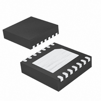
DS4424N+T&R Maxim Integrated Products, DS4424N+T&R Datasheet - Page 9

DS4424N+T&R
Manufacturer Part Number
DS4424N+T&R
Description
IC DAC 7BIT 4CH 5.5V 14-TDFN
Manufacturer
Maxim Integrated Products
Datasheet
1.DS4422NTR.pdf
(11 pages)
Specifications of DS4424N+T&R
Number Of Bits
7
Data Interface
Serial
Number Of Converters
4
Voltage Supply Source
Single Supply
Operating Temperature
-40°C ~ 85°C
Mounting Type
Surface Mount
Package / Case
14-TDFN Exposed Pad
Lead Free Status / RoHS Status
Lead free / RoHS Compliant
Power Dissipation (max)
-
Settling Time
-
In this example, the Typical Operating Circuit is used
as a base to create Figure 3, a DC-DC output voltage
of 2.0V with ±20% margin. The adjustable power sup-
ply has a DC-DC converter output voltage, V
2.0V and a DC-DC converter feedback voltage, V
0.8V. To determine the relationship of R
start with the equation:
Substituting V
ship between R
I
current for the DS4422/DS4424). Summing the currents
into the feedback node produces the following:
Where:
Figure 3. Example Application Circuit
OUT0
is chosen to be 100µA (midrange source/sink
*V
OUT
FB
AND V
for an Adjustable Power Supply
Applications Information
0A
Two-/Four-Channel, I
V
= 0.8V and V
4.7kΩ
FB
FB
I
_______________________________________________________________________________________
and R
OUT0
R
VALUES ARE DETERMINED BY THE DC-DC CONVERTER AND SHOULD NOT BE CONFUSED WITH V
=
0A
I
R0B
R
0B
≈ 1.5 x R
0A + 0B
= I
R
=
R0B
Example Calculations
is determined to be:
0B
4.7kΩ
R
V
R
FB
0B
OUT
- I
SDA
SCL
A1
A0
GND
0B
R0A
× V
= 2.0V, the relation-
OUT
DS4422/
DS4424
FS0
V
CC
0A
R
FS0
and R
= 80kΩ
OUT
OUT0
FB
, of
, of
0B
,
And:
To create a 20% margin in the supply voltage, the value
of V
is calculated to be 2.67kΩ, and R
4.00kΩ. The current DAC in this configuration allows
the output voltage to be moved linearly from 1.6V to
2.4V using 127 settings. This corresponds to a resolu-
tion of 6.3mV/step.
To achieve the best results when using the DS4422/
DS4424, decouple the power supply with a 0.01µF or
0.1µF capacitor. Use a high-quality ceramic surface-
mount capacitor if possible. Surface-mount compo-
nents minimize lead inductance, which improves
performance, and ceramic capacitors tend to have
adequate high-frequency response for decoupling
applications.
Given that the absolute maximum rating for the OUT
pins is V
power rail be brought up before or at the same time as
the power rail of the source it is controlling.
CONVERTER
DC-DC
V
OUT
CC
2
I
OUT0
C, 7-Bit Sink/Source
CC
is set to 2.4V. With these values in place, R
OUT
FB
+ 0.5V, it is recommended that the DS4424
I
I
0A
0B
V
OUT
I
OUT
R0A
* = 2.0V
AND V
Power Rail Considerations
R
R
0A
0B
=
= 2.67kΩ
= 4.00kΩ
RFS
Current DAC
V
OUT
OF THE DS4422/DS4424.
R
0A
V
−
FB
* = 0.8V
V
0A
FB
V
is calculated to be
CC
Decoupling
0B
9


